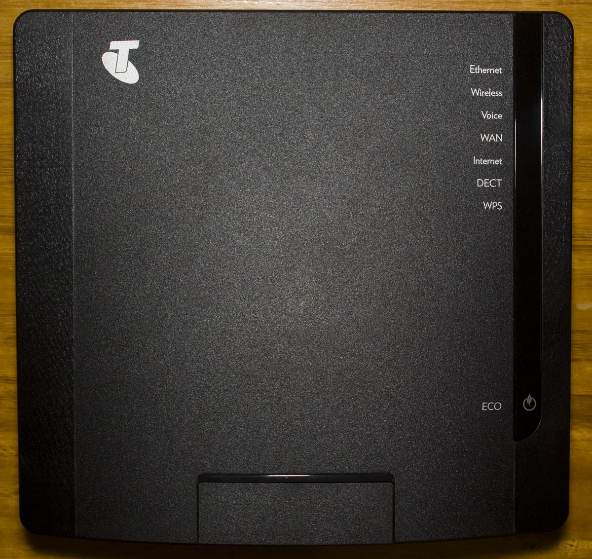
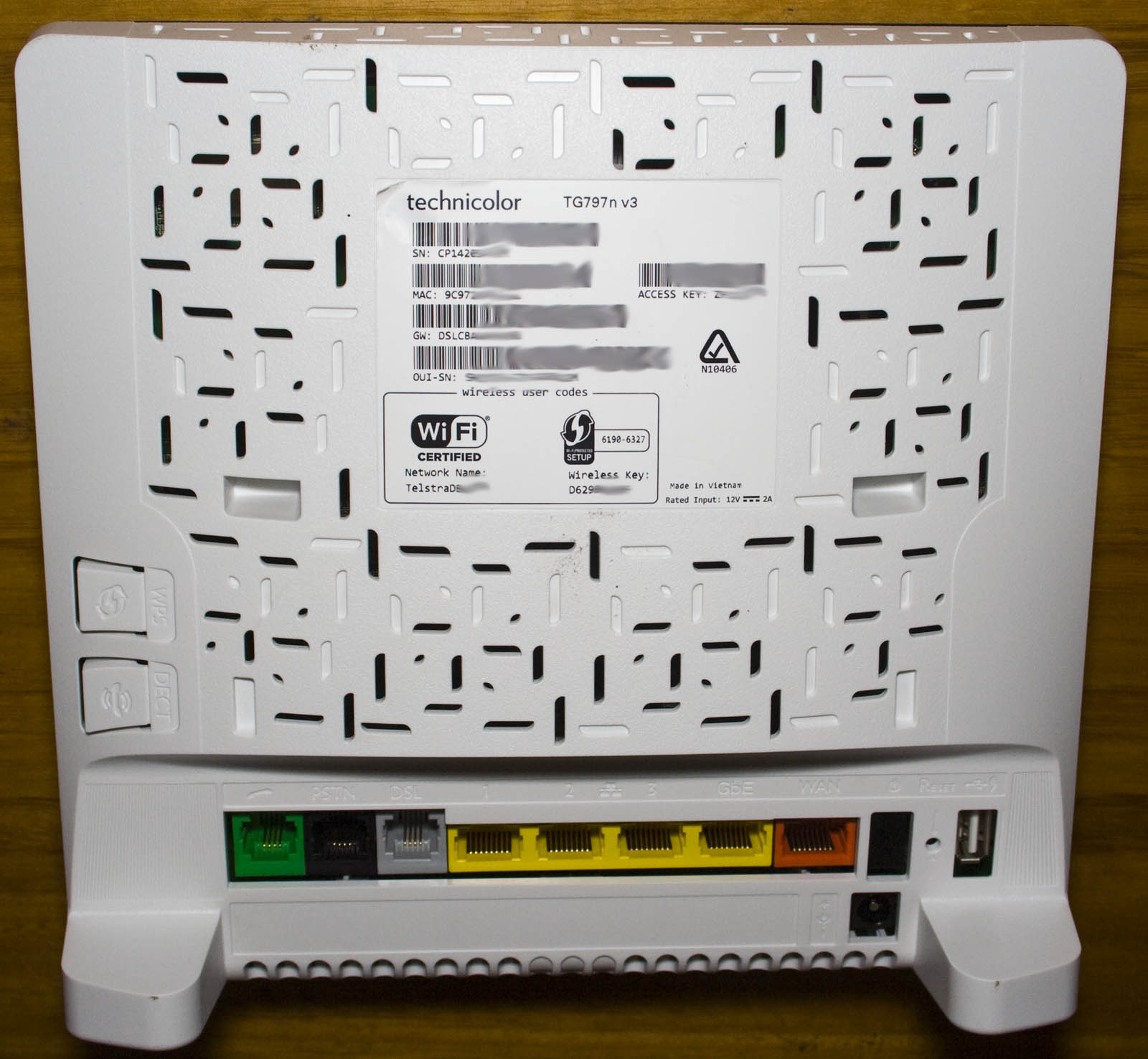
Today we’ll be taking a look at the Technicolor TG797n v3 Router (Telstra branded), an ADSL2+ Wireless router with 1 gigabit WAN and LAN port, 3 10/100 ports, VOIP, DECT and 2 USB ports. Once again this is another router which I haven’t heard of this brand before. It looks to be similar to the Thomson Gateway TG797.
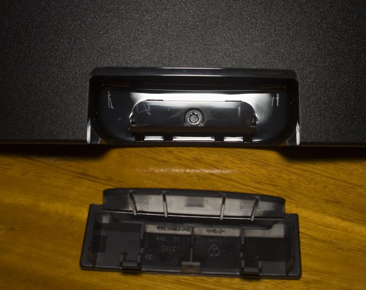
2 screws later and we’re in. There’s a small removable panel at the front which looks to be for a DECT cradle.
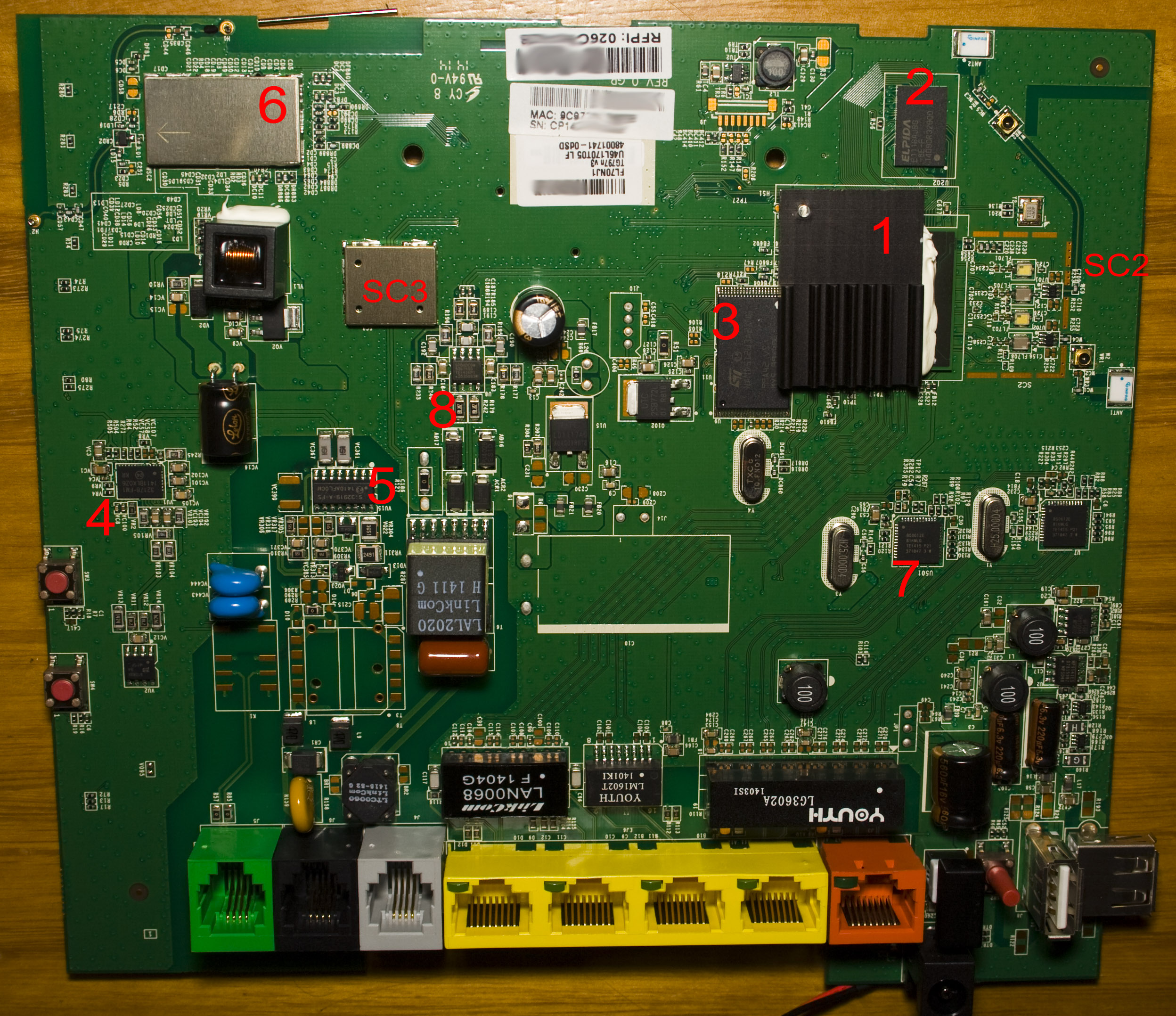
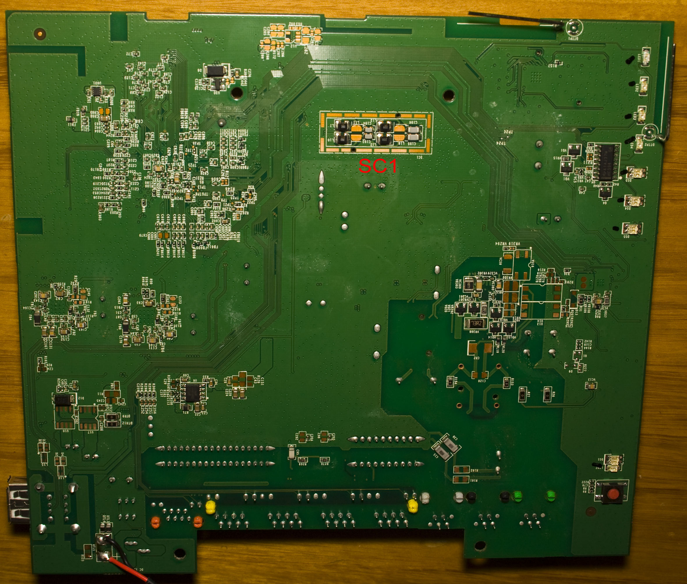
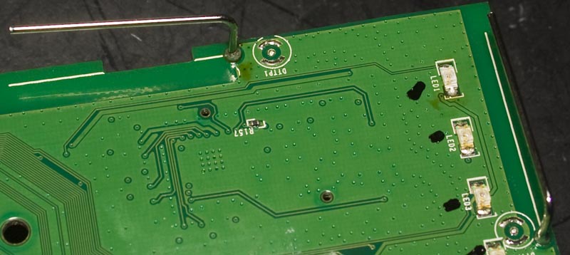
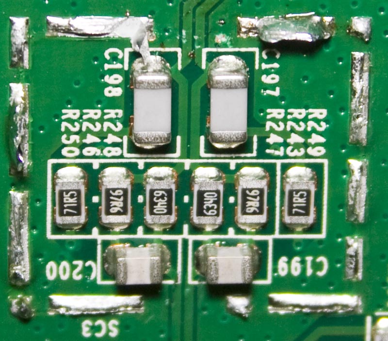
We’ve got a MP9141ES and 2x MP1492 SMPS near the input jack, an UTC LD1117 LDO and we’ve got Lelon branded electrolytic capacitors, there is a outline in the middle of the PCB for a very large capacitor. The PCB date code is 14th week of 2014 so it’s pretty recent. The heatsink that’s on top of the main chip has been soldered down using what looks like a nail on the top left and some epoxy to hold it down, the heatsink has a foot print which could have been a bit bigger. There are two metal cans, one for the DECT radio and one for something else labelled SC – which there are two more labels on the PCB, I can only assume it means “Special Circuit” or similar.
Looks like we’re missing the transformer from the PSTN black port but it’s still active and the green port is inactive according to the manual. There are 3 different transformers for the Ethernet ports, 1 that covers 2 gigabit ports, 1 for 1 LAN port and another one for 2 LAN ports.
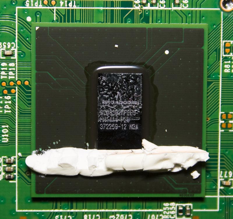
1. Broadcom ADSL2+, 802.11n and DECT SoC
Has dual cores running at 400MHz, 2×2 802.11n with 2.4/5GHz support, ADSL2+ transceiver, 4x 100Mbit Ethernet PHYs, DECT, VoIP and USB support. Running from a 10MHz crystal and a 20MHz oscillator.
BCM6362
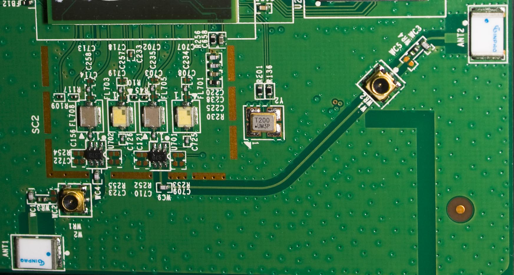
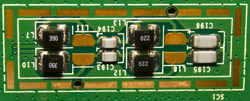
SC2
Near the main chip we have the Wifi circuit with two small ceramic antennas and U.FL connectors also available.
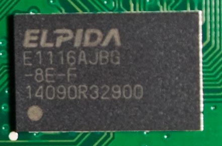
2. Elpida 1Gbit DDR2 SDRAM
E1116A
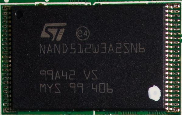
3. ST 512Mbit NAND Flash
NAND512W3A2S
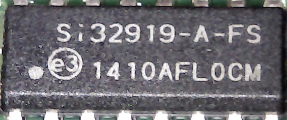
4 + 5. Silicon Labs Telecom Interface
Si32178 + Si32919
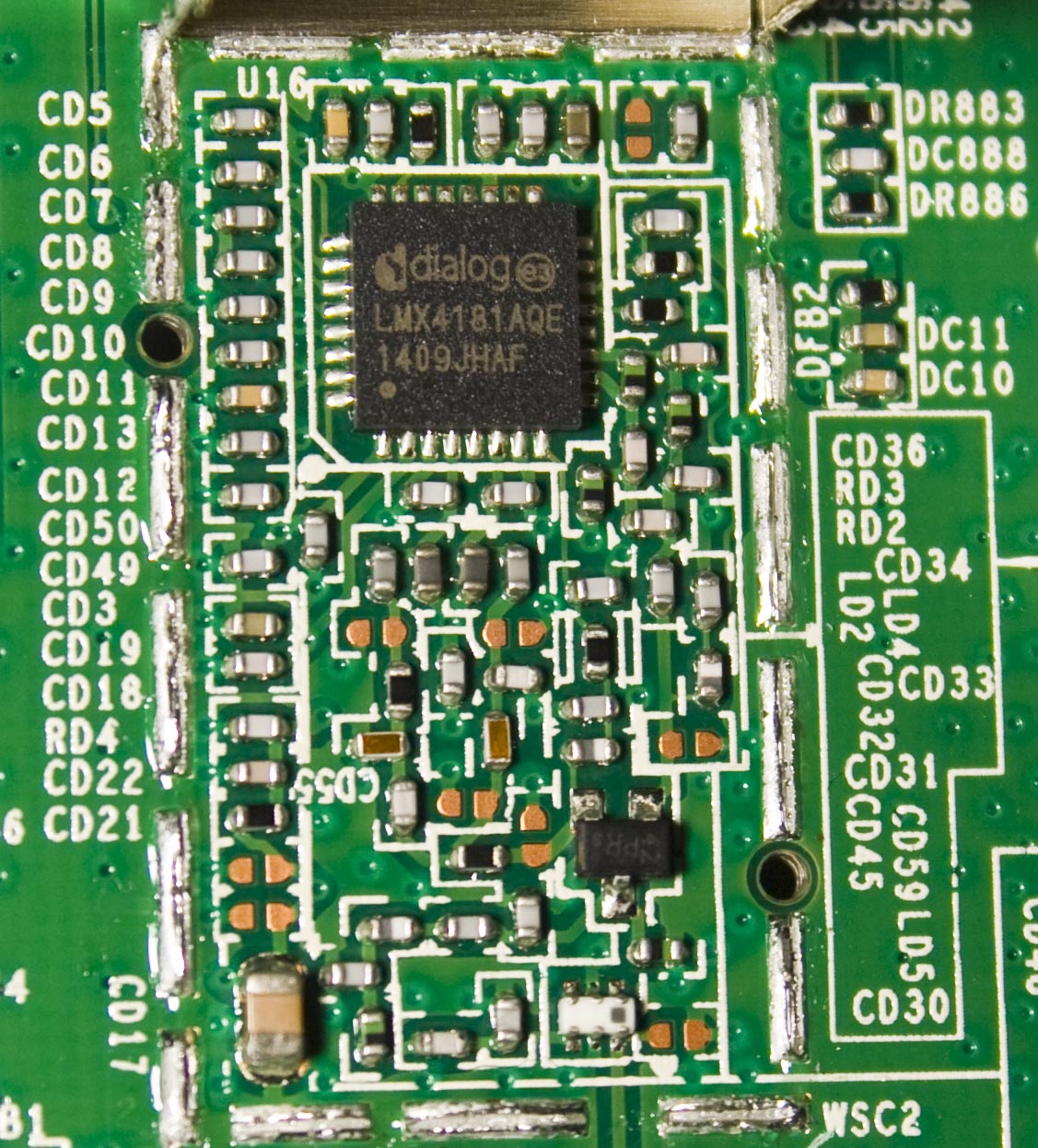
6. Dialog Radio Transceiver for DECT + Antennas
LMX4181AQE – Dialog_Leaflet
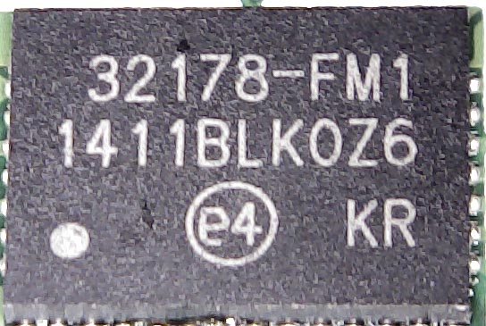
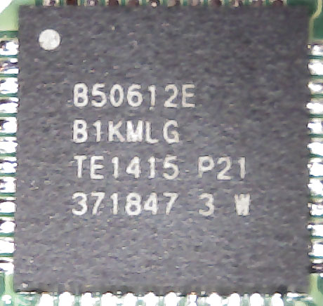
7. Broadcom Gigabit Ethernet PHY x 2
With 25MHz crystal
B50612E
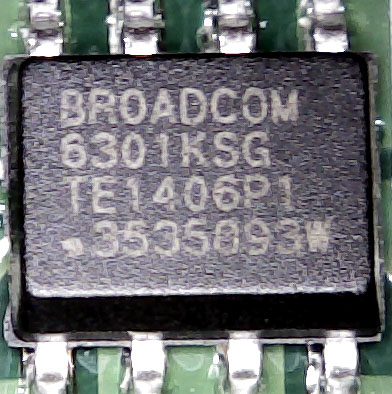
8. Broadcom ADSL2+ Line Driver
BCM6301
SC3
Under the metal can we’ve got some resistors and capacitors, connects to the transformer on the modem line and to SC1
SC1
Some capacitors and inductors, connects to the main chip
And that’s all.


I have one of this. CPU runs at 400mhz or from a 10MHz crystal and a 20MHz oscillator ?
I think the CPU core runs from the 10MHz and the 20MHz oscillator is fed into the chip for the Wifi.
Hi,
Would there be anyway of attaching an external antenna? wifi range is rubbish!
Hi Jimmy,
Yes, near the SC2 circuit there are 2x u.FL connectors where you can plug in external antennas. They have u.FL to RP-SMA/SMA cables on Ebay if you’d like to hook it up to an existing antenna.
Hi,
I would like to know how to physically disable wifi on this mainboard.
Hi there!
Dear I have got the 797n v3 modem
I’m from Malaysia so can u guide me how to connect this modem to my home internet line
Malik +60123510718
Hello there
My TG797n v3 apparently “died” after a power surge. Is there a replaceable fuse inside.
I took out 2 screws but the Dect appears to be holding (how to release?)
I know this is a somewhat old post, but The uF.L connectors are reverse wired, ie, the outside part of the brass connector is the centre wire signal carrier – Weird. To prove it, I soldered a 10M shielded cable inner wire with ordinary modem aerial on the other end directly to one of the “u.FL’s” and presto, range extended somewhat, but worked even better when soldered directly to the rail of the Ceramic Aerial/s. Did not connect/solder the shield to anything.
Tests and simple observation showed that these u.FL’s are joined directly to each other ( to perhaps facilitate post production testing only?). Anyway, nothing really makes this outmoded dinosaur much better.
I know this is a somewhat old post, but The uF.L connectors are reverse wired, ie, the outside part of the brass connector is the centre wire signal carrier – Weird. To prove it, I soldered a 10M shielded cable inner wire with ordinary modem aerial on the other end directly to one of the “u.FL’s” and presto, range extended somewhat, but worked even better when soldered directly to the rail of the Ceramic Aerial/s. Did not connect/solder the shield to anything
Any have the boardview.brd and the schematic.
Thanks