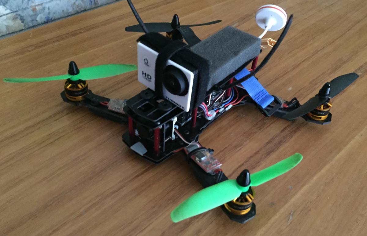
I’ve mentioned before that I’ve been looking into quadcopters and built my ZMR250 quadcopter a few months ago which is working well, a few modifications have been made here and there; and some are still to come.
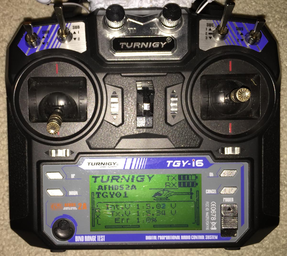
One problem with the transmitter is that there isn’t a way that I’ve found to make it beep or light up if you exceed a certain communication error rate, the further you go or the more objects in your line of sight, the higher the error rate becomes. You can glance down at the remote and check it there but when you are focused on your FPV monitor you can easily forgot so I would like a better way. There may be a way to do it in software but I decided to try the hardware route.
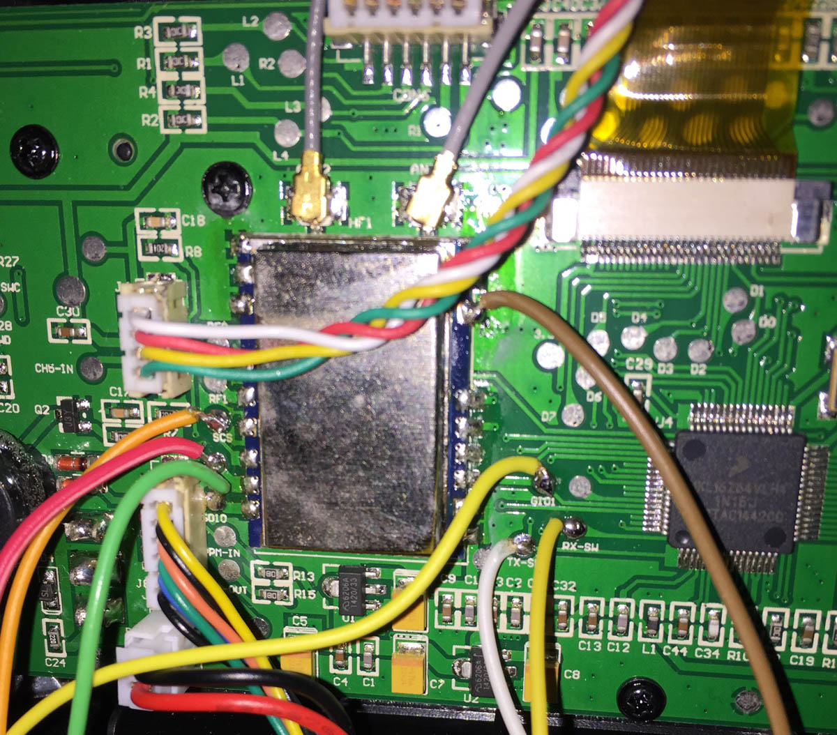
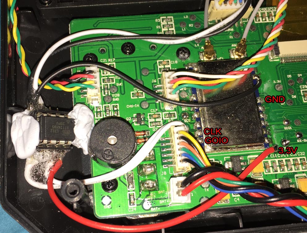
To start, I thought I’d go digging around the transmitter to see if I could find an RSSI pin by measuring voltages when I had the receiver on the quadcopter in an open space and then compare to in a microwave (as it blocks most of the 2.4GHz radio). I couldn’t find an RSSI pin so it was time to break out the logic analyser and capture data from the radio module, there had to be some communication between the MCU and radio module in order for it to display on the LCD.
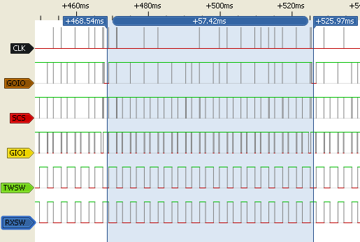
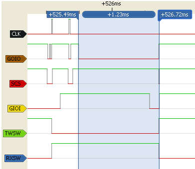
Once thing that was very noticeable was the GOIO pin would pulse low for about 1.2ms every 57ms when it was in range. When the error rate got higher, it would drop to 150ms and sometimes 300ms but after more testing it seemed unreliable.
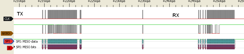
When the transmitter and receiver are paired we see the initial TX and then the RX packet, I decoded it using SPI, there was a clock of ~6MHz and 1 data line GOIO. Inspecting both packets gave some similarities but nothing that stood out. After a few more attempts of trying to figure it out I jumped over to the scope, something that I should have done sooner.
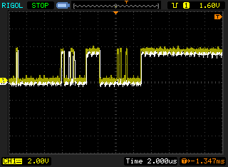
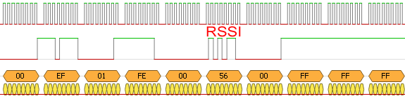
I applied one close by RX packet as a reference (white) and then captured an RX packet when in the microwave (yellow) to compare the two, after a bit of analysis I found one byte that changed depending on the error rate, as you can see in close proximity there is basically no error. The RSSI byte is found in the RX packet occurring after the FE and 00 bytes.
Now we can move to the code side, I was thinking about using an external shift register to read the serial data but after testing different methods and wanting to keep things simple I settled with using an ATtiny25/45/85’s Universal Serial Interface (USI) to read the incoming data. At a 6MHz serial clock we’ll have to use an AVR clock double that frequency so I went with 16MHz with the PLL like I’ve done before.
// Initialise USI properly, wait for GOIO pin high for a while
uint8_t counter = 0;
while (1) {
	if (PINB & (1<<goioIn)) {
		counter++;
		if (counter >= 30) {
			USICR = (1<<USIWM0) | (1<<USICS1); // Enable USI
			break;
		}
	}
	else {
		counter = 0;
	}
}
With the 6MHz serial clock we don’t have that much time to spare and after testing a few methods, the most reliable method was to initialise the USI after the data pin was high for some time. USI is enabled with external clock input and two wire mode.
while (!(USISR & (1<<USIOIF))); // Wait until new serial data received
USISR |= (1<<USIOIF); // Clear received flag
if (USIBR == 0xFE) { // FE byte
    while (!(USISR & (1<<USIOIF)));
    USISR |= (1<<USIOIF);
    if (USIBR == 0x00) { // 00 byte
        while (!(USISR & (1<<USIOIF)));
        USISR |= (1<<USIOIF);

        // RSSI byte
        if (USIBR >= RSSI_COMPARE_TO) { // Change to suit your error rate needs
            OCR0A = USIBR;
            led_on = 1;
        }
        else {
            OCR0A = 0;
            led_on = 0;
        }
    }
}

// Timer overflow
ISR(TIM0_OVF_vect) {
    if (led_on == 1) {
        PORTB |= (1<<led);
    }
}

// Timer OCR0A compare match
ISR(TIMER0_COMPA_vect) {
    PORTB &= ~(1<<led);
}
We monitor the USI and wait until a byte is received, then quickly clear the received flag so we can accept another byte and look for the FE and 00 bytes before reading the RSSI byte. Testing is required on the RSSI_COMPARE_TO until the LED turns on at the error rate that we need, for me I wanted it to turn on around 50-70% or so. Download TGY-i6_RSSI_LED_Indicator_v1.0
I put the ATtiny in an IC socket, glued the wires in place and blu-tacked it down, then put the LED above the monitor in the monitor cover.
https://www.youtube.com/watch?v=qMDcZc0PiiA
And here’s a video to show it in action.


Hallo Alex
Sorry for my bad english. I have learn english a little bit 50 Years ago.I have buy a Turnigy-i6
Now i found two Firmenware on the Hobbyking Side.Can you tell me what Version of this two Firmeware i need ? I have the Receiver 6B with Telemetrie Option.
Question two : When i have two Quads i must bind two Receiver . What i have to do ?
Thanks for Help and Respect for what you now about electronics.
Hi Wolfgang,
My TGY-i6 is running v1.1 – 15 Oct 2014 from when I bought it and it works fine. You shouldn’t need to update the firmware unless there is some feature or fix they come out with that you would like. I have heard of users flashing their firmware with the FlySky i6.
With 2 quads, you just need to change the model memory – Hold Ok, press ok, Model select, change to Model 2, hold cancel for the beep, then press cancel a few more times. It will show the model as “TGY 02”, then power off. Put the receiver in bind mode, hold down the “Bind Range Test” button and power up. Remove the bind connector from the receiver and power off the TGY-i6 TX. Power it back up and confirm it binded ok. Now you can do the same for the other models, just change to Model 3 and re-bind another receiver, etc.
So since we know it is sending the RSSI info back to the transmitter, how can we get this useful information over to our Flight Controller or OSD board for display on our video overlay?
Any idea where to pull this info from the IA6 or IA6B receivers?
Thansk!
That sounds like a good idea, I’ll have open one up and check it out.
I’ve been able to find the pin on the MCU which is giving out the same byte stream as the transmitter with the RSSI byte being in the same location, CLK and DATA pins shown in the picture. The clock speed is 1MHz but there is 4 clock pulse here and there instead of always been 8 all the time so I’ll need to rework the code a bit because it doesn’t work at the moment and then add PWM output to work with MW OSD.
Edit: The 4 clocks even out and I ended up having to use negative clock edge (spent a while to figure that out). 50Hz PWM generation is done, now I just need to combine it all together and test.
This is cool, thanks! Please keep us posted on the progress… There was a reddit thread where someone indicated that on the IA6B receiver the RSSI data is part of the PPM stream. I havent been able to confirm this yet though.
Yep I’ve done a post on it – https://www.insidegadgets.com/2015/11/25/extracting-ia6-receiver-rssi-and-outputting-to-osd-for-fpv-display/
Works for iA6B v2 too.
Why are you not using the buzzer for the RSSI-alarm? This would be useful when flying FPV without OSD. It could work the same as the battery alarm.
Hi Sebastian,
Initially I did think of doing that but I didn’t really want something beeping at me (because sometimes it jumps to a high error rate for just a split second), so I went with the LED option. But it wouldn’t be too hard to add the buzzer option at all, you can grab the output and use a transistor or mosfet to switch 5V to the buzzer.
Very nice page!!!
This code works in arduino nano too?
Can you help me with this?
Tks
Excuse my ignorance, I don’t know what to do with the code…. 🙁
I’ll keep investigating. I assume it needs compiling. Someone here mentioned it works with a Nano. I have programmed an Arduino as an ISP so I just need to figure out how to load this onto an ATTiny44.
Any help will be appreciated.
Hi Ryan,
I’m assuming that you mean ATtiny45.
Firstly download and install WinAVR (assuming you have Windows) – http://winavr.sourceforge.net/
In my downloaded zip file, find the main.elf file and copy it to C:\WinAVR-20100110\bin
Check you have the ATtiny hooked up to the Arduino like this – http://highlowtech.org/?p=1706
Open command prompt, cd to C:\WinAVR-20100110\bin and run these two commands:
avrdude -p ATtiny45 -c usbtiny -U lfuse:w:0xe1:m -U hfuse:w:0xdf:m -U efuse:w:0xff:m
avrdude -p attiny45 -c usbtiny -U flash:w:main.hex
Hi Alex,
Thanks for the information. It is an ATTiny44A (http://www.communica.co.za/Catalog/Details/P0381364468). Clearly bought the wrong thing! AARG. Will see what I can get today.
I’ll see if I can get one of these today:
http://www.communica.co.za/Catalog/Details/P0852176404
http://www.communica.co.za/Catalog/Details/P1256362028
I’ll check it out later.
Hi Alex,
Finally getting somewhere.
Got an attiny85. Flashed 16mhz pll bootloader. Completed the 2 cmds with success which then uploaded the sketch. When the tiny starts, the led flashes once and goes off. Then the led stays off. If I unplug the iusr wires the led comes on. If I walk outside away from my quad and get up to 80% error, the led does not flash or come on.
I’ve got clk connected to pin 3 (pb2) and the soio connected to pin 6 (pb5). The led on pin 5 (pb4).
What am I doing wrong?
Really stoked to get this far. Are you able to rewrite the code in arduino?
Ok. Maybe I’m being a plank again.
I’ve installed the ia6b avg main.hex file. I also changed the -p parameter to attiny85. So perhaps the fuse parameters are different aswell.
Hi Ryan,
Could you please re-confirm your wiring for GOIO, should go to the bottom right pin – PB0 pin5.
It sounds like the fuses were programmed correctly, otherwise you would see the LED on for 1.6 seconds. It should only be on for about 100 milliseconds.
Also on the picture I have, make sure that your ground is connected to where my black wire goes (for some reason my GND label in the picture looks like it goes to one of the RF can pins). Also feel free to post a picture with your wiring too.
Hi Alex,
I tried moving the connection on the TX to GI01 from SOI0 (the one below the SCK connection). I also tried moving the connection on the tiny to PB0 – no joy.
I’m going to flash this now: https://www.insidegadgets.com/wp-content/uploads/2015/09/TGY-i6_RSSI_LED_Indicator_v1.0.zip
Here are the pics:
https://dl.dropboxusercontent.com/u/42018361/20161210_083333.jpg
https://dl.dropboxusercontent.com/u/42018361/20161210_083342.jpg
Hi Ryan,
Looks like I thought the bottom left of the RF can was GOIO (I couldn’t really see if it was a G in my TX) but in your picture, I see it’s SOIO. So the way you can it before was correct. Did you also pick up that other ATtiny board, it could be the other components on the current board might interfere with it’s operation.
Ok. I think I’m just gonna buy a taranis.
I love arduino and gadgets but this is more than expected. I actually need to be able to diagnose this. So another arduino receiving info from this one. I have a diy oscilloscope from banggood but I don’t know how to use it well enough.
I use telemetry, would it be possible to extract in TX the data received from telemetry? Vbt, Alt, Dist among others? Thanks