From the last part, I talked about some of the ideas I had for the Alarm system v3, two of which we’ll look at today, using the Si4432 module and the ESP8266 Wifi module.
The Si4432 module is has an adjustable frequency range of 240MHz to 930MHz so you could use any frequency you wanted but to keep it legal I’ll use a frequency between 433.075 to 434.775MHz. The input voltage is 1.8V to 3.6V, you have the option to adjust your transmit power from 1dBm to 20dBm (17mA to 85mA), we have RSSI available and have TX and RX FIFO buffer of 64 bytes. An interesting feature is that you can disable the FIFO and access the RX/TX of the chip in direct mode in real time, something that could be useful for streaming applications. We can also have interrupts on RX received and TX transmission complete.
I bought a couple off Ebay, used the RadioHead RF22 library and hooked up the TX and RX to 2 Arduinos and it worked well, the default frequency is 434MHz. Range wise I didn’t have any problems in the garage or outside.
I started increasing the output power and once I reached anything higher than 8dB, the receive text became corrupted, adding a 100uF capacitor on the TX helped and then I added a 10uF capacitor on the module itself to reach 17dB but it occasionally still resulted in corrupted text, I think I’ll still to 8dB or less.
By default the speed/modulation is set to FSK, No Manchester, Rb = 19.2kbs, Fd = 9.6kHz which takes about 10.7ms to transmit a packet. That’s a bit slow so I changed it a bit higher 57.6kbs and it’s down to 1.3ms for a transmit for a simple “Hello World!” message. I extracted only the necessary code from the RH library and tried it out on an AVR MCU, I went with the ATtiny84A which I’ve used before in v2 of the alarm system, a while later I had an example TX/RX working successfully.
// ATtiny24/44/84 Pin map
//
//                       +-\/-+
//                 VCC  1|o   |14  GND
//                 PB0  2|    |13  PA0 LED
//                 PB1  3|    |12  PA1
//                 PB3  4|    |11  PA2 Si4432 SS/nSEL (9)
//                 PB2  5|    |10  PA3 Si4432 IRQ (10)
//                 PA7  6|    |9   PA4 Si4432 SCLK (8)
//  Si4432 SDI (6) PA6  7|    |8   PA5 Si4432 SDO (7)
//                       +----+
Above is how I had it hooked up to the ATtiny84.
RX / TX modes and checks
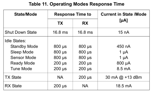
The Si4432 has a series of idle states, in shutdown state it takes 16ms to wake up whilst in standby/sleep/sensor mode it’s 800uS, for the clients I think I’ll go with the standby/sleep state whilst for the server it can be on ready mode as current isn’t a problem.
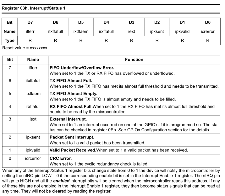
In order to check if an packet arrives or if our packet has been sent we need to check the register 03h, the ipksent and ipkvalid bits.
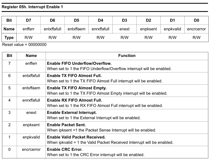
However we need these bits to be cleared when an event occurs, so we need to enable the interrupts on register 05h so that when the interrupt occurs, reading the interrupt status 03h will then clear those bits after the read otherwise the bits would stay as 1 after the event occured.
TX Header – From / To addresses and checks
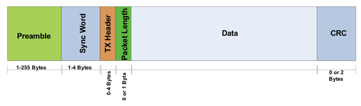
The Si4432 gives us a bit of flexibility on the packet structure length, we have have adjustable lengths for the preamble, sync word, tx header, etc, most of which we can leave the defaults but what I’m interested in for the moment is the TX Header. It’s basically 4 bytes that we can specify that the Si4432 can use for internal hardware matching and only accept the packet if the bytes we want match.
The RH library uses the TX header for the to address, from address, id and flags, we can change this to anything we like. For me, I’ll have these as to address, from address, request type and state, which allows us have the client/server only listen out for their address, we have a complete byte to use for the address where as the nRF24 only allowed for ~6 hardware addresses.
spi_write_reg (RH_RF22_REG_32_HEADER_CONTROL1, RH_RF22_HDCH_HEADER3);
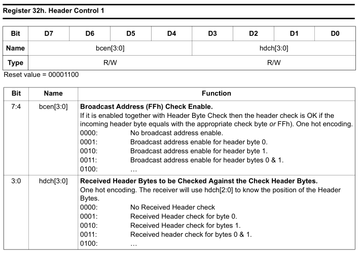
We can check the AN440 which has details on the registers and find the section which does the TX header checking, it’s register 32h. Firstly we need to make sure that broadcasting address checks are disabled (by default RH library has them enabled so any RF22 broadcasting can talk to any other) and then we have to select which TX Header bytes we’d like to do checking on. RH library has byte 3 (1000) enabled which is the to address so that’s suits me too.
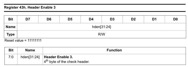
Si4432 also allows for individual bits in the TX header to be checked, so if you only wanted bit 7 of byte 3 to be compared that can be accomplished by settings the bits in 43h, by default it checks the whole byte which is what we want in our example.
spi_write_reg (RH_RF22_REG_3F_CHECK_HEADER3, RH_SENSOR_NO);
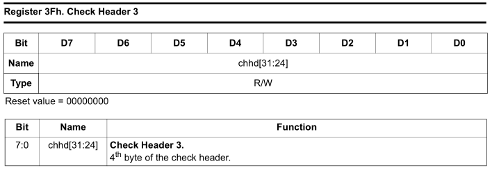
We just need to tell it what to compare it to in register 3Fh, we load our sensor number to this address so now before the Si4432 accepts a packet it needs to match this address.
Code
#define RH_SENSOR_NO 0x01
...
uint8_t RH_RF22_init(void) {
...
// Speed and modulation
RH_RF22_setModemConfig(FSK_Rb57_6Fd28_8);
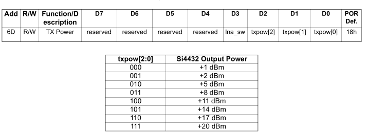
// Power
RH_RF22_setTxPower(RH_RF22_TXPOW_8DBM);
RH_RF22_sleep(); // Sleep mode
spi_write_reg(RH_RF22_REG_05_INTERRUPT_ENABLE1, RH_RF22_IPKVALID | RH_RF22_ENPKSENT);
// Set our to address to check for incoming packets that match
spi_write_reg(RH_RF22_REG_3F_CHECK_HEADER3, RH_SENSOR_NO);
The TX/RX share the RH initialisation code, I’ve just modified it a little bit with the changes discussed earlier, changing the modulation/speed, power, setting it to sleep mode, only enabling the interrupt we would like and then setting out address as the to address.
uint8_t validPacket = false;
while (validPacket == false) {
  RH_RF22_resetFifos();
  RH_RF22_setModeRx();

  uint8_t readReg = 0;
  uint8_t timeoutCounter = 0;
  while (!(readReg & ipkvalid)) {
    readReg = spi_read_reg(RH_RF22_REG_03_INTERRUPT_STATUS1);
    _delay_ms(5);

    timeoutCounter++;
    if (timeoutCounter >= 50) {
      RH_RF22_setModeRx();
      RH_RF22_resetFifos();
    }
  }
}
clear_data_in();

// Read from address
uint8_t fromAddress = spi_read_reg(RH_RF22_REG_48_RECEIVED_HEADER2);

// Read the packet
uint8_t packetlength = spi_read_reg(RH_RF22_REG_4B_RECEIVED_PACKET_LENGTH);
spiBurstRead(RH_RF22_REG_7F_FIFO_ACCESS, dataIn, packetlength);

// Check the type of request
uint8_t requestType = spi_read_reg(RH_RF22_REG_49_RECEIVED_HEADER1);
if (requestType == CHECK_IN) { // Client check in
	if (strncmp("Hello World!", (char*) dataIn, 12) == 0) {
		PORTA |= (1<<PA0);
		_delay_ms(50);
		PORTA &= ~(1<<PA0);
	}
}
Firstly on the RX side, we reset the FIFOs, set RX mode and read the interrupt status register to see if we have received a valid packet, for some reason if you don’t delay a few milliseconds, it doesn’t work but even then when you do there is a high chance that it will lock up, so I added a timeout counter. It could possibly be that I’m sending data to it too fast as when sending data slowly it doesn’t lock up, only the RX locks up, the TX keeps sending packets just fine.
You could also just use the interrupt pin which I will likely do later on (but even with that it also locks up). We clear our dataIn variable, read the from address (just in case we need to reply back in the future) and then read the packet length and then the packet; the good thing is that the packet can have variable length. Because I wanted to use the TX header, we check to see what sort of request it is and then if the data matches “Hello World!”.
RH_RF22_resetFifos();

RH_RF22_txHeaderTo = RH_SENSOR1;
RH_RF22_txHeaderRequestType = CHECK_IN;

uint8_t data_out[] = "Hello World!";
RH_RF22_send(data_out, sizeof(data_out));

// Wait for packet to be sent
uint8_t readReg = 0;
while (!(readReg & enpksent)) {
	readReg = spi_read_reg(RH_RF22_REG_03_INTERRUPT_STATUS1);
	_delay_ms(5);
}
On the TX side it’s simple, we clear the FIFOs, set the to / request type, our data and then call the send command. We then check the same interrupt status register to see if the packet has been sent.
Download ATtiny84_Si4432_Test
ESP8266
I bought the ESP8266 (ESP-12-E) as I heard good things about them and how they could be used a small webservers, I could potentially use it to replace the RPI, plus I saw what cnlohr was doing with them which seemed very cool so it was about time I took a look.
At first I spent some time firing up a Linux VM, downloading / compiling the ESP8266 SDK, etc and trying out the demo example and cnlohr‘s work too, it took a long time for me to get up and running. Once I did get up and running, I started to look through the code and wondered how I would go about changing it to suit my application.
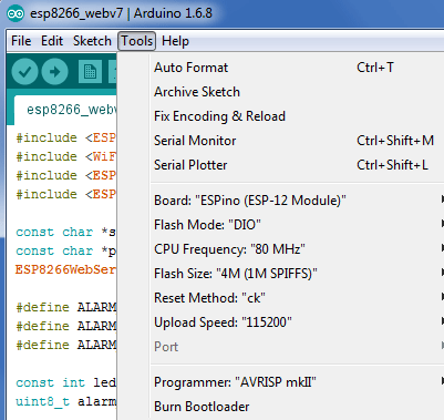
Long story short, I didn’t go that route, instead I saw that there was an Arduino style software which could run on the 8266. It seemed very simple to install and in a matter of minutes I was up and running, I found the webserver example and could easily just see the code I need to change, nice.
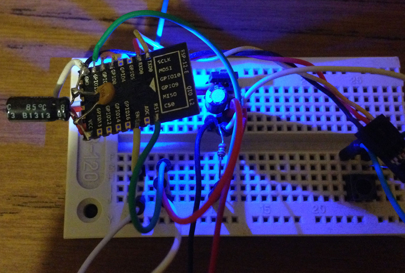
GPIO0 pull up with 1.5K to 3.3V with button to ground
GPIO15 pull down with 1.5K to ground
EN and RST to 3.3V
The 8266 connects via serial to the Arduino (or via a Serial to USB converter but the only one I had didn’t work), there seem to be a few ways to wire up the 8266 pins but the way that worked with my module was as above. If you wish to re-program the 8266 you power it off, hold down the button to enter the programming mode, power it on, you see the LED blink, then you can let go of the power button and upload the new code.
After a bit of playing around, I started to have some crashes when reloading pages, seemed to happen randomly, eventually I found out that using chars[] with too much data was causing these problems, switched over to Strings and haven’t had any crashes since.
if (readInput[0] == 'S') {
const char delim[2] = "-";
char *token = strtok(readInput, delim);

uint8_t sensorNo = 0;
uint8_t tokcount = 0;
while(token != NULL) {
  if (tokcount == 1) { // Sensor number
	 if (atoi(token) <= 0 || atoi(token) >= 20) { // Out of bounds
		break;
	 }

	 sensorNo = atoi(token) - 1;
	 Serial.print("number is ");
	 Serial.println(sensorNo+1);
  }
  ...
The 8266 will just be my front end, all data will be stored on the ATmega, we can easily transfer data via USART to the 8266 either when the ATmega receives a successful check in from a sensor or maybe every 5-15 seconds. For example, we can parse a string such as S-1-Kitchen-3.5V-53-s- with the code above, which would represent sensor 1 in the kitchen reads 3.5V and last checked in 53 seconds ago. We can use the Arduino to send the serial commands to test it all out. The ATmega may need to use external SRAM or EEPROM if we don’t have enough space to store everything in.
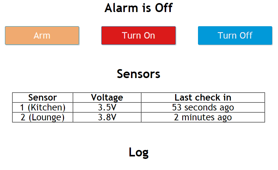
This is how it looks at the moment, it’s large text/buttons to suit phones more than PCs. I think I’ll also add the type of sensor, the zone, if the sensor is armed to this too and also have a way to update each sensor’s information from the web interface too. The log would show when the alarm state changes and which sensor triggered the alarm, so I’ll need to add a real time clock to the ATmega. Download esp8266_webtest
That’s all for this part, I now know that the Si4432 works and so does the ESP8266 as a webserver. For the next part, I’ll have to look into the getting the Atmel CryptoAuthentication chip up and running.


you have any cord suppored to attiny85
Hi Dear
i have got a SI4432 module and want to use it as signal generator .Need its carrier for my project no other functionality at this time required.Need help how can I program arduino uno , mini etc can you guide about and library using which I can change the carrier frequency of SI4432.
regards