Since making the the Wireless Gameboy Controller, there were some ideas thrown around about making other devices of it wireless, one of them was the Gameboy Link Cable which we’re going to look at today.
(sneak peak)
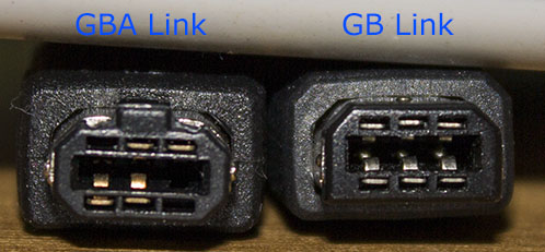
There are different link cables – one for the Gameboy and another for the GBA. I ordered both but only the Gameboy link cable had all the pins on the connector where as the GBA only had the ones it needed. The GBA connector won’t fit in the Gameboy but the Gameboy connector will fit into the GBA.
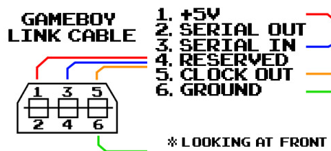
Let’s take a look at the link cable pinout. We have 5V, serial out, serial in, clock out and ground, seems easy enough.
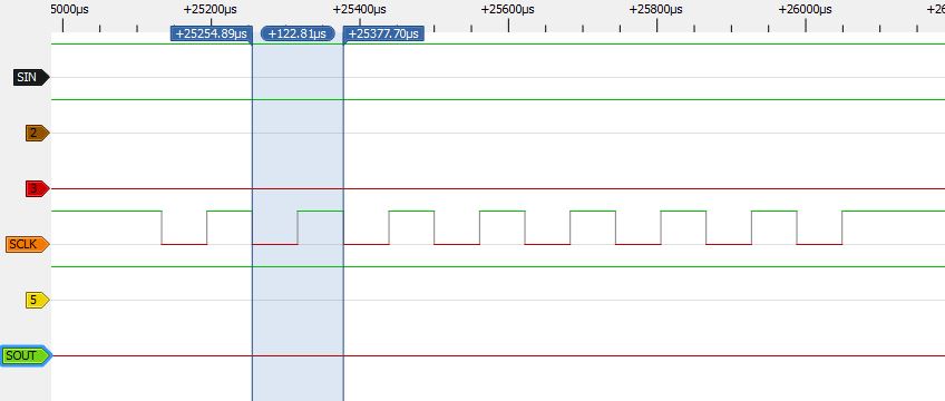
Out comes the logic analyser to take a look at the signals, the game I was trying the multiplayer on was F1 Race and with just 1 end of the cable connected. We can see the clock is slow (120us per cycle) and that the serial in is high, serial out is low so it doesn’t seem to be sending anything. The F1 Race game shows that you are the only player in the game and you can continue on to the race.
When the other side is plugged in, we can see the SIN goes low. F1 Race now waits on the screen like we are waiting for other players.
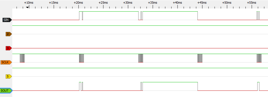
Once both players are racing together, we can see some data being exchanged.
On a closer look, it looks like data is exchanged on each clock cycle for serial in and out which isn’t good news for us. The nRF24 is a packet based system so there is no way for us to send and receive data at the same time. There could be a way to have the game repeat a transmission or more likely you could patch the game to allow for packed based transactions but then you’d need a flash cart.
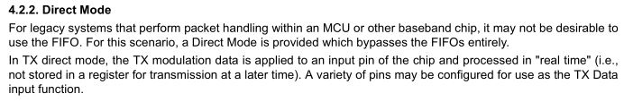
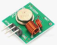
Another way around it could be to use direct mode radios such as the Si4432 which seems to have support of it or those cheap 433MHz modules but in either case you would need 2 or 3 radios but it’s impractical to do.
I gave up on the idea of compatible Wireless Gameboy link for existing games and will just proceed with the packet based system which we can control ourselves. As an example, we’ll re-use the 2 Player Pong game I did with the Wireless Gameboy Controller.
; Load serial data
LD		a,E
LD		(0xFF01), a

; Transmit
LD		a, #0x81
LD		(0xFF02), a

... some delay later ...

; Load HL as serial data 0xFF01
LD		HL,#0xFF01

; Read data
LD		E,(HL)
LD		D,#0
Let’s firstly understand how to send and receive serial data with the Gameboy, the GBDev site gives us an explanation. Basically it’s a shift register, you write your 1 byte of data to 0xFF01, set 0xFF02 as 0x81 which starts the transfer and sets the clock as the internal Gameboy’s clock (you could choose to go double speed if wanted to).
We can then either wait for the interrupt or just wait a little while – 1ms should be enough for the data to clock out/in. We read 0xFF01 and the clocked in data is there.
senddata(player1x); // 6 writes/reads
delay(1);
player2x = receivedata(0);

senddata(player1y);
delay(1);
player2y = receivedata(0);

senddata(ballx);
delay(1);
senddata(bally);
delay(1);
senddata(player1Score);
delay(1);
senddata(player2Score);
delay(1);
With the 2 Player Pong game, the server sends 6 bytes (player1x, player2y, ballx, bally, score1, score2) and receives 6 bytes but only 2 are actually used (player2x, player2y). You will notice we delay 1ms and then read in the data if required.
As long each side sends each other a packet at the start (or have some default start up values), we could have both Gameboy’s think they are the master so they clock out the data and an MCU will read each incoming bit and write the outgoing bit.
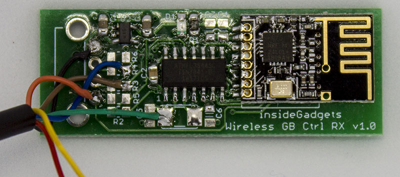
For the MCU side, I’ll just re-use the WGC USB RX board and wire up the link cable to that.
ISR(PCINT0_vect) {
	if (!(PINA & (1<<GB_CLK))) {
		// Read bytes to send while writing bytes last received
		read_and_write_bytes(6);

		transmitData = 1;
		_delay_us(50); // Wait a little so we don't re-trigger the interrupt
We’ll enable the PA0 interrupt so we’re waiting for the clock line to go low and check to see if any new packets have arrived. Once the PA0 line goes low, we write/read out 6 bytes and then transmit a packet; there isn’t too much to it. It just took a little while to get the reading/writing of bits working properly but every now and then it can be a bit glitchy, usually restarting one of the Gameboy’s helps it.
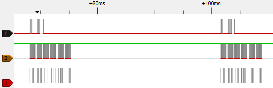
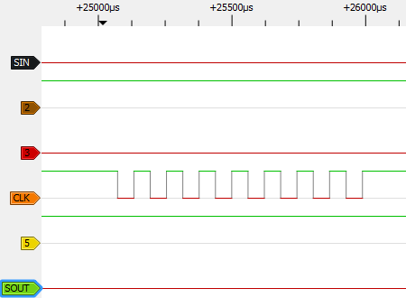
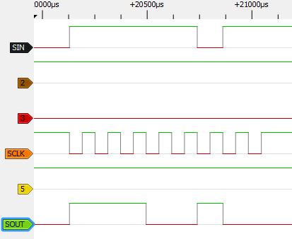
Here’s how it looks at the moment with the logic analyser, you could always shorten the delay time in-between each 6 byte transfer if you wanted it to go faster.


Hello
Does the “GB Link” cable you show above fit into a DMG?
If so, where did you find a fully populated one? I really need one for a project.
Hi, unfortunately they don’t fit into a DMG, they are too small.
Hi, it is not possible to use ESP8266 directly without any MCU?
I think is possible tbh. I’ll try to work on it.
Something like that can be used imo
What do you think about?
The ESP8266 has an MCU on board that is reprogrammable so you can use it but power consumption of it is pretty high so battery life will be affected