Previously we were able to use 2 carts to communicate to each other to play Pong with a little mod and some code changes. This time as per some users request, we’ll be taking a look at adding a Gamecube receiver which will emulate a Gamecube controller. This could be useful if you wanted to play Gameboy games on the Game Boy Player or the Virtual Console / GC mode on the Wii.
(sneak peak) – Now available
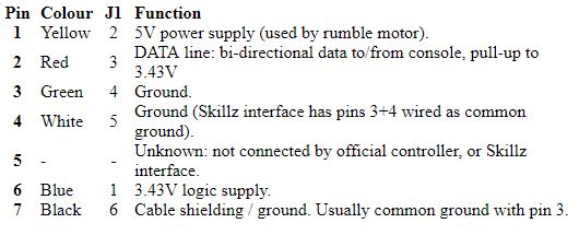
After a quick check on what was out there already about the Gamecube controller interface, I came across the int03 site which gives us the controller pin out and that it’s a serial interface which is held high to 3.4V and is pulled low.
It looks like the Gamecube polls the controller which replies back with the button presses however the website mentioned that at first the Gamecube sends eight 0’s but they don’t appear to have the communication after that, how they reach the Gamecube requesting the controller state.
It looks like we’ll have to capture the initial communication with a logic analyser and also re-confirm their findings so I took apart my Gamecube controller and wired it up to take a look.
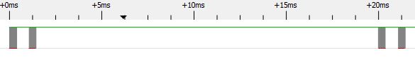
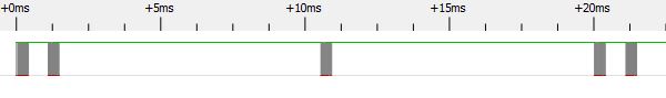
Firstly it seems like the Gamecube polls the controller at varying polling times, it may depend on whether you are in the system menu or could possibly depend on the game. We have a poll then 1ms later another poll which might be for debouncing and then 19ms after we have another 2 polls. On another instance we have the first two polls then a poll after 9ms and then the other 2 afterwards.

Lets have a closer look at the initial communication between them as there is quite a bit going on it seems.
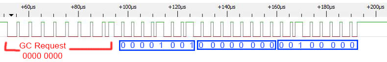
It does appear that the GC requests 0x00, we have a stop bit (which also looks like a 1) and then the controller replies back with 0x09, 0x00, 0x20. What do these bytes do? I’m not sure, but it could be sending back something about the controller, what it might support, etc.
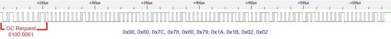
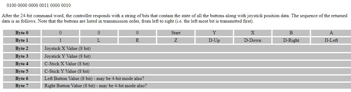
Next I assume the GC requests another byte because the next series of bytes looks to start off as the int03 website said the controller sends back (0x00, 0x80) but it seems to have 2 bytes more at the end.
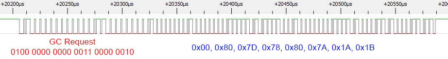
Lastly the controller polling request does indeed match the int03 website and then the controller responses with key press data. Edit: The GC request text is incorrect, the last byte is actually 0000 0000. I think the high bit only appears when rumble is occuring?
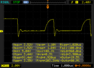
A quick look at the signal on the scope doesn’t look that great but let’s continue. We basically just have to read the 2 initial requests from the GC and send back the appropriate data and then it should keep polling for the controller update.
After some playing around, verifying on the logic analyser to get timings right, I was able to get reading and writing to work. It is achievable with the internal 8MHz oscillator but timing has to be just right so I went with a 16MHz crystal. At first I used an NPN transistor but the rise time of the data line was slow when the transistor was switched off so I went with an N mosfet which did the trick.
There are 2 little things I found while doing so, firstly if we don’t send back a controller update when the GC requests it, it goes back to sending the first 0x00 request which makes sense as the controller may have been unplugged. Secondly if the GC is reset, it also goes back to sending the first 0x00 request too, so we need a way to check for this.
if (gcInputBuffer[0] == 0) {
	GIMSK &= !(1<<PCIE0); // Turn off interrupts

	// Wait for initial request from Gamecube (0000 0000)
	// Transmit Gamecube controller reply 1
	read_bytes(1);
	while (gcInputBuffer[0] != 0) {
		_delay_ms(10);
		read_bytes(1);
	}
	write_bytes(gcReply1, 3);

	// Gamecube responds (0100 0001)
	// Transmit Gamecube controller reply 2
	read_bytes(1);
	write_bytes(gcReply2, 10);

	// Turn on pin interrupt
	_delay_us(50); // Wait a little
	PCMSK0 |= (1<<PCINT0);
	GIMSK |= (1<<PCIE0);
When we receive a byte which reads 0x00, we know either the GC was first powered on, reset or perhaps we may be out of sync so we re-read the input until we see 0x00 again and if not we delay a little bit of time. This is more just to try and not land in the middle when GC is transmitting the first byte. As you can see, we use interrupts, so by the time we are out of the interrupt after reading 0x00, it may be too late to send the reply.
After we send our 3 byte reply, we wait to read the next byte (don’t care what it is) and send out 10 byte reply back. We wait a little bit so our pin change interrupt won’t be triggered by our-self and then turn the interrupt on.
ISR(PCINT0_vect) {
	if (!(PINA & (1<<DATA_IN))) {
		PORTA &= ~(1<<LED);

		// Read 3 bytes, assume it's the Gamecube poll (0100 0000 0000 0011 0000 0010)
		for (uint8_t byte = 0; byte < 3; byte++) {
			uint8_t dataIn = 0;
			for (uint8_t x = 0x80; x != 0; x >>= 1) { // Loop 8 times (fast)
				if (read_bit()) {
					dataIn |= x;
				}
			}
			gcInputBuffer[byte] = dataIn;
		}
		while (!(PINA & (1<<DATA_IN))); // Wait until high
		_delay_us(1);

		// Write the controller data
		write_bytes(gcControllerData, 8);

		_delay_us(50);
	}
}
When the interrupt is triggered, we check to see if the data in is low and go into reading the bytes quickly as there isn’t much time to read the first bit of data. After the 3 bytes are read, we send the controller data (actually we should probably do a quick check to see if the first byte is 0x00 before sending anything back), then delay a little bit like before.
if (mirf_status() & (1<<RX_DR)) {
	PORTA |= (1<<LED);
	mirf_CE_lo; // Stop listening

	mirf_CSN_lo; // Pull down chip select
	spi_transfer(R_RX_PAYLOAD); // Send cmd to read rx payload
	kpData = spi_transfer(0); // Read data
	mirf_CSN_hi; // Pull up chip select
	mirf_config_register(STATUS,(1<<RX_DR)); // Reset status register

	mirf_flush_rx_tx(); // Flush TX/RX
	mirf_CE_hi; // Start listening
	PORTA &= ~(1<<LED);

	...

	gcControllerData[0] = 0;
	gcControllerData[1] = 0x80;
	gcControllerData[2] = 0x7D;
	gcControllerData[3] = 0x78;
	if (kpData & 0x01) { // A
		gcControllerData[0] |= 0x01;
	}
	if (kpData & 0x02) { // B
		gcControllerData[0] |= 0x02;
	}
	...
}
_delay_us(250);
When we aren’t interrupted, we just check if there are any packets waiting for us and if so, update the controller data respectively. The most time consuming part of this was getting the read and writing timing just right (you also have to add stop bits), both inside and outside the interrupt (as some things are skipped inside the interrupt).
Download Wireless_Gameboy_Controller_RX_Gamecube_v1.0
Part 1
Part 2: Adding RF channel/address configuration and more testing
Part 3: Communicating between carts for 2 Player games
Part 4: Adding a Gamecube Receiver
Part 5: Adding a Super Nintendo Receiver
Part 6: Making the GBA TX Cart


