Previously we add some configuration options for the nRF module and did more testing on the Wireless Gameboy Controller. Today we’re going to look at how we can have 2 of the carts communicate to each other so it’s possible to play a 2 player game such as Pong.
(sneak peak)
The first thing we need to figure out is how we will get ATmega to output data to the Gameboy because at the moment we’re currently using the ATmega to read what the Gameboy puts on the address/data lines. If we tried to read from anything at the moment, the flash chip would be the device outputting data.
What if we cut the A15 line going into the flash chip’s CE line and change it to A14? This means that anything from 0x0000 to 0x3FFF will set the CE line active but then anything from 0x4000 to 0x7FFF will set it not active. This means that nothing will be outputting data if the Gameboy requests it, so if the ATmega can respond quickly enough, it could output data and the Gameboy would pick it up. But by doing this we are limiting ourselves to 16KB ROM size.
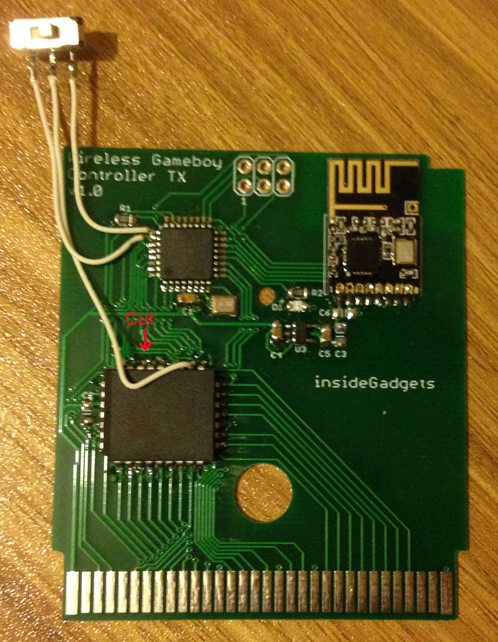
One problem is that the flash chip I chose uses the 0x5555 flash instructions which means we do need A15 to go to CE when flashing the chip. Not too much of an issue, I just wired up a DPDT switch for that purpose.
LD (0x7000), a
NOP
NOP
NOP

; Read data
LD E,(HL)
Let’s try to read data to see what it might look like with a logic analyser. We’ll write some data first and then try to read data.
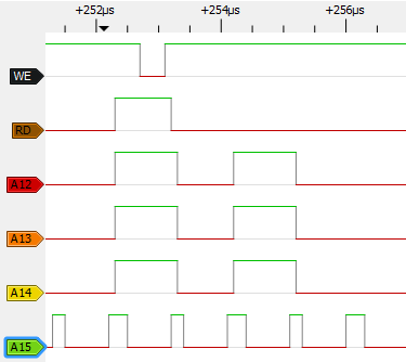
When writing we can see the WE line going down, RD goes high and A12-A14 is high. For reading, the RD line goes low straight away and it stays low pretty much forever until we do another write, so we can’t use the RD line for anything useful like we can with the WE line. We can see that the A12-14 lines go high again so it looks like that’s where the read occurs.
I thought what I’d do is keep the write first (doesn’t matter what we write), use A15 to determine when we should be ready to output data. Of course this means we’ll have to play around with timings to suit, we don’t really need the A15 pin anyway as we could just NOP the right number of cycles anyway.
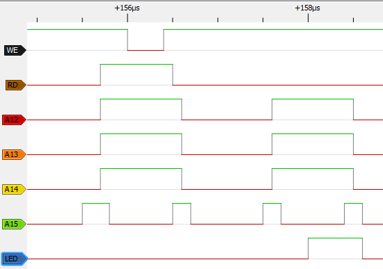
So after some tests and playing around, it does seem like the ATmega can output data and it be received by the Gameboy reliably, you can see me triggering an LED to turn on right at the correct spot. I had to assume it was about the same spot as when the WE line goes low.
if ((readAddr & 0x1F) == 0x07) { // Address 0x7000 and WR low
	if (stage == 0) { // Read the number of bytes we will receive from the GB to send to the nRF
		bytesToSend = readData;
		sendCounter = 0;
		receiveCounter = 0;
		stage++;
	}
	else if (stage == 1) { // Store the bytes now
		if (sendCounter < bytesToSend) {
			dataOut[sendCounter] = readData;
			sendCounter++;
		}
		if (sendCounter == bytesToSend) { // Finished, next stage
			stage++;
		}
	}
With that out of the way, now we need to write data and receive data in stages, say write 4 bytes, read 4 bytes, etc. I thought it would be nice to tell the ATmega how many writes/receives to expect before writing or reading them. Stage 0 is the number of bytes we will receive from the Gameboy to the ATmega then we go to stage 2 which reads out the bytes at each WE low pulse.
else if (stage == 2) { // Read the number of bytes we want to receive from the nRF
	bytesToReceive = readData;

	if (dataInCount == bytesToReceive) { // Has to match the payload size for now
		stage++;
	}
	else {
		bytesToReceive = 0;
		stage = 0;
	}

	while (!(PINC & 0x08)); // Wait for A15 to go high
	asm volatile("nop"); // NOP a couple of times until the GB is ready to receive the data
	asm volatile("nop");

	PORTD = bytesToReceive; // Change to the data
	DDRD = 0xFF; // All pins as outputs
	PORTB |= (1<<LED);
	asm volatile("nop");

	// Change back to input
	DDRD = 0x00;
	PORTD = 0x00;
	PORTB &= ~(1<<LED);

	// Pre-load the first byte to write
	nextByteWrite = dataIn[receiveCounter];
}
Stage 3 is when the bytes to receive from the ATmega/nRF is read, if it matches the payload size, we write the byte back to the Gameboy so it knows how many bytes to read out. This would be good if we had the nRF24 dynamic payload size in use, but I haven’t looked into that as yet.
We wait for A15 to go high, nop a few times and then change the data pins as outputs, output the data, wait 2 cycles (the LED counts as 1) and change the data back as inputs. I also had to pre-load the first byte to write because it seemed like reading from the array took more cycles than I thought it would.
else if (stage == 3) { // Write the bytes now
	if (receiveCounter < bytesToReceive) {
		while (!(PINC & 0x08)); // Wait for A15 to go high
		asm volatile("nop"); // NOP a couple of times until the GB is ready to receive the data
		asm volatile("nop");

		// Change to the data and set as output
		PORTD = nextByteWrite;
		DDRD = 0xFF;
		PORTB |= (1<<LED);
		asm volatile("nop");

		// Change back to input
		DDRD = 0x00;
		PORTD = 0x00;
		PORTB &= ~(1<<LED);

		receiveCounter++;
		nextByteWrite = dataIn[receiveCounter];
	}
	if (receiveCounter == bytesToReceive) {
		stage = 0;
	}
}
For the final stage, we output the data from the array to the Gameboy, one byte at a time each WE/RD cycle until we finish and then reset back to stage 0.
if (stage == 0) {
	mirf_CE_lo; // Stop listening
	if (mirf_status() & (1<<RX_DR)) {
		mirf_CSN_lo; // Pull down chip select
		spi_transfer(R_RX_PAYLOAD); // Send cmd to read rx payload
		spi_read_data(dataIn, mirf_PAYLOAD); // Read payload

		mirf_CSN_hi; // Pull up chip select
		mirf_config_register(STATUS,(1<<RX_DR)); // Reset status register

		mirf_flush_rx_tx(); // Flush TX/RX
	}

	mirf_transmit_data(4);

	NRF_RX_POWERUP;
	_delay_us(130);
	mirf_flush_rx_tx(); // Flush TX/RX
	mirf_CE_hi; // Start listening
}
We have to fit in when to transmit or receive data from the nRF module, seems suitable to have it transmit a packet and wait to receives packets just before we are waiting for the WE line to go low if we are waiting for the first stage.
Now I just had to build a game to show the communication so I thought a quick game of Pong might work, shouldn’t be too difficult and there isn’t much to transmit or receive. One GB will act as a server (by holding down A at boot) and transmit it’s x/y (really all we need is y) and the ball location while the other will receive this data and transmit it’s x/y. I should have also had the server transmit the score too (didn’t think of that at the time).
Once I powered up the server and then the client, it worked first go! Another option which a user suggested is making the link cable wireless which sounds like a good idea to explore, this would mean you wouldn’t need special carts.
Download 2_Player_Pong_v1.0
Part 1
Part 2: Adding RF channel/address configuration and more testing
Part 3: Communicating between carts for 2 Player games
Part 4: Adding a Gamecube Receiver
Part 5: Adding a Super Nintendo Receiver
Part 6: Making the GBA TX Cart


Great! What you think about a wireless “cable link”? It’s possible?
Hi, yes I do think it should be possible, another user mentioned it as well so it’s on the ideas list. Just waiting for the link cable to arrive then I can play around with it.