Previously we made a Super Nintendo receiver for the Wireless Gameboy Controller but it would nice to add L & R support so that some games on the SNES could also be playable and it would also allow GBA games to be played which used the L & R buttons so that’s what we’ll do, make a GBA TX cart.
(sneak peak)
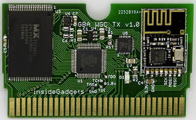
One of the problems is the GBA carts size, it’s half the size of the Gameboy cart so we don’t have a lot of room to work with and we need to fit a CPLD, flash chip, AVR MCU and the nRF24L01+. After a bit of browsing around trying to find the smallest CPLD & MCU, I came back to the Altera 5M80Z which I was looking at for a flash cart but didn’t go ahead with it due to the 0.4mm pin pitch but it’s basically the only choice.
For the AVR MCU, it doesn’t need a whole lot of I/O or anything special, so I settled with the lowest cost one, the ATtiny48. It runs at 8MHz max so it isn’t that fast and doesn’t have an option for an external crystal. I suspect that even if it could run at 16/20MHz it may not be fast enough for detecting data from the GBA so what I decided to do instead was have the CPLD communicate to the ATtiny48 directly; once data was ready it could potentially just set a pin high and then read out the data whenever it wants.
We didn’t need a CPLD with the Gameboy TX cart but we’ll need one for the GBA due to the way the GBA uses all 24 pins to set the address then latches the lower 16 bits of the address by setting CE low and it uses the lower 16 pins to read/write 16 bits of data. There is a way to increment the lower 16 bits by pulsing the RD pin which is also used. In some ways it’s easier than having to make an MBC like on flash carts.
After having a rough idea of what I was going to do, I spent a while making the PCB, quite a difficult one, was able to do it with just 2 layers. I also included small pads for the CPLD which I would use pogo pins on. The first revision of the boards arrived so I soldered the CPLD and flash chip then got to work on the CPLD code.
CPLD Code
I won’t go through all revisions of the code I tried as there were many ways I tried to re-write the same code, it did work to some degree. Most of the time I could read/write to the flash cart and on the GBA see the Nintendo logo but then got a white screen.
I found that in order for the Nintendo logo to display, they didn’t use RD to increment the address.
But after the logo they started using RD incrementing which is why my code wasn’t working on the CPLD I chose (this CPLD seems to have some problems without a clock).
Eventually I decided that I would stick a 50MHz clock on the CPLD and that’s when things started to work better. After a few code changes I was seeing the screen after the GBA but writing to the cart was sometimes glitchy, it would stop writing at certain addresses. After a bit of research I found that when using clocks, you have to synchronise the inputs by using 2 flip flops which solved the problem.
After playing around a bit more, I was using the reset pin to reset some of the registers back to defaults when it booted up and soon realised that I didn’t need to worry about any of that.
always @ (posedge clock) begin
	inputCESync <= inputCE;
	inputCESafe <= inputCESync;
	inputRDSync <= inputRD;
	inputRDSafe <= inputRDSync;
	inputWRSync <= inputWR;
	inputWRSafe <= inputWRSync;

	// Latch address when CE goes low
	if (!inputCESafe && !addressLatched) begin
		outputAddress <= inputAddress;
		addressLatched <= 1'b1;
		addressIncrement <= 1'b0;
	end
	if (inputCESafe) begin
		addressLatched <= 1'b0;
	end

	// Increment address when RD is pulsed
	if (addressLatched && !inputRDSafe) begin
		addressIncrement <= 1'b1;
	end
	if (addressLatched && addressIncrement && inputRDSafe) begin
		outputAddress <= outputAddress + 16'd1;
		addressIncrement <= 1'b0;
		outputReady <= 1'b0;
	end

	// Set output to AVR
	if (addressLatched && !inputWRSafe) begin
		outputReady <= 1'b1;
		inputDataSync <= inputAddress[6:0];
		outputData <= inputDataSync;
	end
end
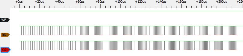
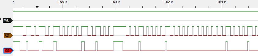
Here’s the final code I have, every clock cycle we sync the CE, RD and WR inputs. When the address is placed on the bus and CE goes low, we latch the address as long as the address hasn’t already been latched and we set our lower 16 bit output address of the flash chip to be the lower 16 bit input address.
If the address is latched and then RD goes low, we set a variable to addressIncrement to 1 so we know if RD goes high later on, we should increment the address. Once RD goes high, we add 1 to the output address and reset the addressIncrement variable.
If we notice that WR goes low, we know that a write is being performed so we set a pin high, capture 7 bits of the data byte and set the outputData variable which is directly connected to the AVR.
Later on we’ll see that the GBA software uses writes to output the key press data just like the Gameboy TX cart did. Why only 7 bits? It’s because I wanted to save $1 by downgrading to the 5M40Z, it was the only way it would fit the 40 LEs! It’s not a problem, we can just do multiple writes.
ATtiny48 Code
We can mostly re-use the GB TX cart code so there isn’t a whole lot to change apart from just interfacing with the CPLD.
// Wait for first byte to sync up
uint8_t byteRead = 0;
while (byteRead != 0x49) {
	while (!(PINC & (1<<CPLD_TRIG)));
	byteRead = PIND & 0x7F;
	while (PINC & (1<<CPLD_TRIG));
}
I decided it may be a good idea to send one a write so that the ATtiny48 can sync up with the CPLD at the start, any other writes that may happen before the GBA program starts will be ignored. Luckily for us, the GBA doesn’t use the WR pin for any of it’s internal peripherals like the Gameboy does so we are free to do anything we like with it.
// High 7 bits
while (!(PINC & (1<<CPLD_TRIG))); // Wait for trigger to go high
uint8_t readDataHigh = PIND & 0x7F; // Read data
while (PINC & (1<<CPLD_TRIG)); // Wait for low
_delay_us(1);

// Low 7 bits
while (!(PINC & (1<<CPLD_TRIG)));
uint8_t readDataLow = PIND & 0x7F; // Read data
while (PINC & (1<<CPLD_TRIG));
After we are synced, we’ll read out 7 bits of data twice all the time as we need to send the L & R buttons – 10 bits of data, so 2 packets on the nRF24 side. I also included a GB mode which only sends out 1 packet so it can be compatible with any receivers that haven’t had a firmware update.
GBA Program
I went with DevKitPro for developing the GBA program, it took a little while to get up and running because for some reason they took away the default Programmers Notepad that came with it years ago. Having never developed anything for the GBA, I started off with the template example. Most of the logic will be the same as the GB TX cart but there are things like the 2ms timer and how to write to the cart which need to be looked at as they will be different.
// Setup timer
irqEnable(IRQ_TIMER3);
REG_TM3CNT_L = 65500;
REG_TM3CNT_H = TIMER_START | TIMER_IRQ | TIMER_DIVIDERBITS;

// Halt until timer
asm volatile("swi 2");
Unfortunately there doesn’t seem to be that many resources out for the GBA like there is for GB but I was able to stumble upon this post about timers and after a bit of playing around, it was working. I adjusted the timer to be around 2ms by changing the REG_TM3CNT_L register and measuring the output interval with a scope when writing to the cart.
// Send a byte to the AVR
void sendData (u32 address, u32 data) {
   asm volatile(
	 "mov    r3,%0\n\
		mov    r4,%1\n\
		strh   r4,[r3]\n\
      " :

      :  // No output
      "r" (address), "r" (data) :  // Define the routine inputs (%0,%1,%2).
      "r3", "r4" );
}
For writing to the cart we’ll have to mix ASM and C so I found an example which showed this and once again a bit of playing around lead me to working code, I can write a byte to a certain address and it pulls down the WE line.
sendData(0x8000000, kpInput >> 7); // Keep high bit of lower byte as bit 0
for (u8 volatile x = 0; x < 50; x++) {}
sendData(0x8000000, kpInput & 0x7F);
for (u8 volatile x = 0; x < 50; x++) {}
When writing the key press data to the cart, we need to write to 0x8000000 which is where the cartridge access starts and as mentioned before I’m only using 7 bits out of 8 bits due to the CPLD. After each write is a small amount of time to wait so the AVR can process the request and wait for the next byte of data.
And that’s pretty much it. All in all, the GBA TX cart took a lot longer than the GB TX cart did but it got me into making a GBA cart sooner than I thought and wasn’t too bad once all the problems were ironed out. I had thought about making GBA flash carts but I think I might hold off as it may require a 4 layer PCB and there probably wouldn’t be any advantage over the clone carts.
Part 1
Part 2: Adding RF channel/address configuration and more testing
Part 3: Communicating between carts for 2 Player games
Part 4: Adding a Gamecube Receiver
Part 5: Adding a Super Nintendo Receiver
Part 6: Making the GBA TX Cart


