Previously we put together a Wireless Gameboy Controller using an ATmega to read the key press data which the Gameboy sent at a special address and then it was transmitted via an nRF24L01 to a USB device acting as a HID Joystick controller.
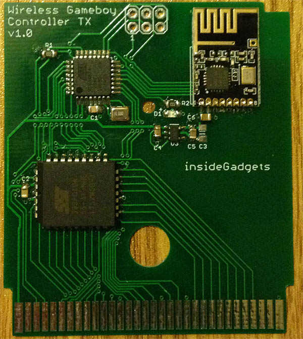
Everything worked nicely so I laid out the cartridge and USB receiver boards, sent it off, received the prototypes.
The cartridge worked first go however when putting on the top half of the case, it was a tight squeeze and was difficult to remove because the nRF module was blocking it’s path, so for the final board I’ll have to move it down a little.
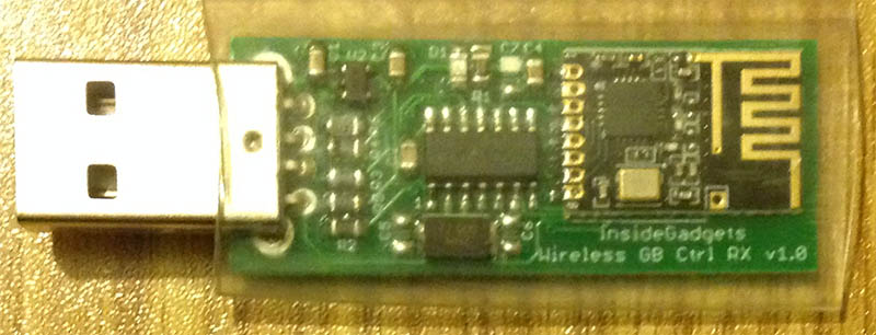
For the USB receiver, I ended up getting the nRF DO/DI pin mixed up so random data was being received. Not to worry though, I recalled that the ATtiny841 swapped the DO/DI pins for whatever reason compared to the ATtiny84. I soldered on the ATtiny841 and it all worked fine too. I’ll put some clear heat shrink over it once testing is complete.
Adding nRF24 Channel/Address configuration
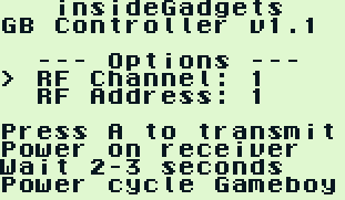
I wanted to add a method of changing and saving the nRF channel/address to the ATmega’s EEPROM so I made the GB program detect if the start button is being held down to boot into the configuration menu. We can now adjust our channel or address, this could be useful if you had multiple receivers and wanted them all to have the same address/channel or if you had some Wifi interference.
if ((readAddr & 0x1F) == 0x06) { // 0x6000 and WR low
	nrfChannel = readData;
}
// RF Address (second stage)
else if ((readAddr & 0x1F) == 0x05) { // Address 0x5000 and WR low
	PORTB |= (1<<LED);
	nrfTx[4] = readData;

	// Update our EEPROM
	eeprom_write_byte((uint8_t*) nrfChannelLocation, nrfChannel);
	eeprom_write_byte((uint8_t*) nrfTxLocation, nrfTx[4]);

	// Update the nRF settings to transmit the data to the RX
	mirf_config_setting_update();

	// Transmit the nrf setting to the receiver until powered off
	dataOut[0] = nrfChannel;
	dataOut[1] = nrfTx[4];
	while (1) {
		mirf_transmit_data(2);
		_delay_ms(50);
	}

	PORTB &= ~(1<<LED);
}
For saving this configuration to the EEPROM we need to choose a different address than 0x7000 which is used for our key presses, I went with 0x5000 for the channel and 0x6000 for the address (of which we only store the last byte of it).
Once the address is received, we save both to the EEPROM and then transmitting to the USB receiver at a fixed address. This means the USB receiver needs a way to change into “configuration receiving mode”, we could use a button but I didn’t have any pins free.
mirf_config_setting_update();
...
// Check for changing of our RX channel/address for 1/2 second
for (uint8_t timer = 0; timer < 10; timer++) {
	if (mirf_status() & (1<<RX_DR)) {
		mirf_CE_lo; // Stop listening
		...
		// Update our EEPROM
		eeprom_write_byte((uint8_t*) nrfChannelLocation, nrfChannel);
		eeprom_write_byte((uint8_t*) nrfRxLocation, nrfRx[4]);

		_delay_ms(250);
		PORTA |= (1<<LED);
		...
I chose to have to start up in this mode, wait for 1/2 a second and then switch back to the channel/address stored in the config. After a bit of playing around, it all worked well. You would press A to transmit the new config, plug in the USB receiver, it will blink twice, you power cycle your Gameboy and then both nRF’s are on the same channel/address.
More Testing
I thought everything was done so I didn’t have to use the 16MHz crystal and could just use the 8MHz internal oscillator.
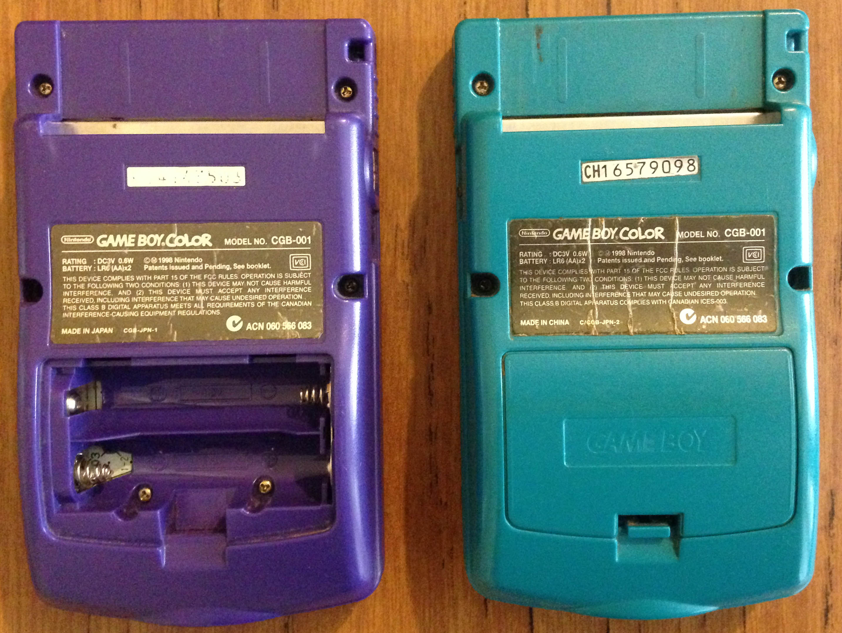
That was until I picked up my other GBC and everything changed. It was CGB-001 just like my other GBC but it was “CGB-JPN-1” where as the one that worked as “C/CGB-JPN-2” a later model. What was happening was that the buttons would randomly be pressed so I played around with adding/removing NOPs without any luck. Luckily I kept the external crystal footprint just in case so I popped on a 16MHz crystal and played around a bit more.
uint8_t readAddr = PINC;
asm volatile("nop");
asm volatile("nop");
uint8_t readData = PIND;

// Verify if address matches, if so transmit data
if (!(PINC & 0x10)) { // Is WR low currently? This means the keypad data we read was correct
	if ((readAddr & 0x1F) == 0x07) { // Was the address 0x7000 and was WR low
		PORTB |= (1<<LED);
		dataOut[0] = readData;
		mirf_transmit_data(1); // Transmit single data byte
		PORTB &= ~(1<<LED);
		kpAddressMatch = 1;
	}
}
It looks like with the GBC it needed a NOP or two before reading the data but once the data is read after that I also re-read the WR pin to make sure it’s still low. This seemed to work fine on some of the GB consoles but not the others.
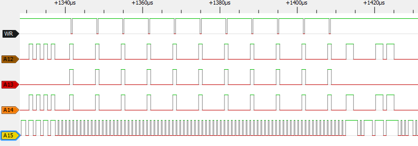
By this time I had played around a fair bit so enough was enough and I broke out the logic analyser to see what was going on. I was sending out the key presses data a few times as you can see WR going low and had 3 NOPs in-between each one. The WR line goes low for around 360ns which isn’t very long so running at 16MHz is a good idea.
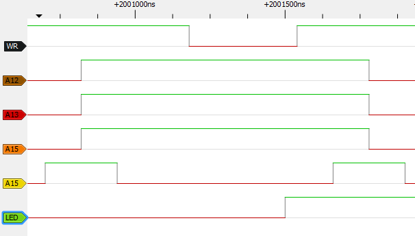
I added in an LED and tried using the pin change interrupt, it’s barely enough to detect WR low.
// Wait for WR to go low
while (PINC & 0x10);
uint8_t readAddr = PINC; // Read address
asm volatile("nop");
uint8_t readData = PIND; // Read data

if ((readAddr & 0x1F) == 0x07) { // Address 0x7000 and WR low
	...
We don’t really need a pin interrupt as there isn’t anything we need to do anyway apart from sending a packet so I just went directly with waiting for WR to go low, read the address, then data and compare the address against 0x7000 which worked nicely.
This means we no longer need to send the same address/data a few times any more and could potentially transmit even more data to 0x7000 provided the ATmega stores it all in a buffer first.
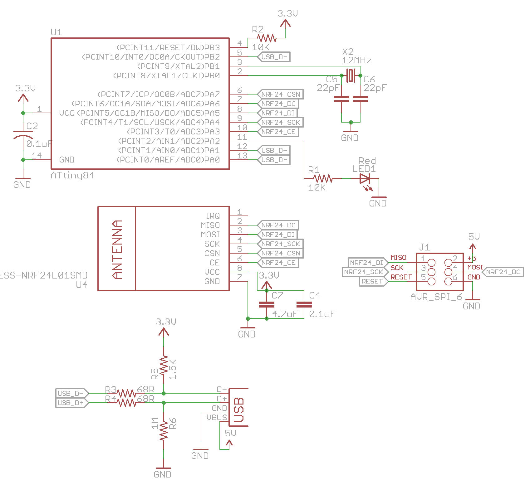
I had to add a NOP for the “CGB-JPN-1” GBC and then it worked perfect on all the consoles, I should have just done this in the first place! Download Wireless Gameboy Controller v1.1, Cart Schematic & USB Schematic.
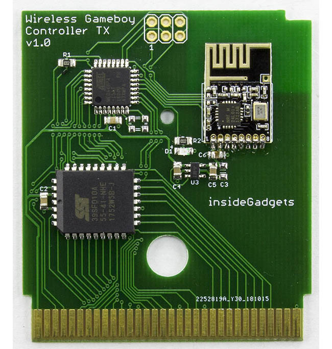
I received the final cart PCBs a few days ago, the case fits well this time and it’s now available on our shop: https://shop.insidegadgets.com/product/wireless-gameboy-controller/
Part 1
Part 2: Adding RF channel/address configuration and more testing
Part 3: Communicating between carts for 2 Player games
Part 4: Adding a Gamecube Receiver
Part 5: Adding a Super Nintendo Receiver
Part 6: Making the GBA TX Cart


