Previously we made a Gamecube receiver which plugged into the Gamecube port which allows you to play Gamecube games, GameBoy games via the Game Boy Player or play Wii Virtual Console or Gamecube games via the Gameboy wirelessly. A few users requested a Super Nintendo receiver which should also work with the GBA Consolizer project, so let’s take a look.
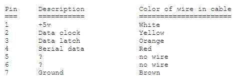
A quick look at the SNES pin out shows that there are 3 lines – clock, latch and data so this should be relatively simple.
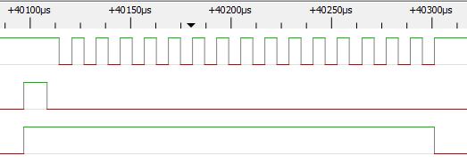
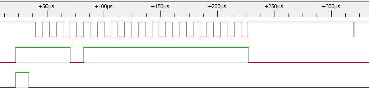
Out with the logic analyser we go, we can see the latch, 16 clocks (clock polarity is low) and the data is high by default. When a key is pressed the data bit for that clock cycle goes low.
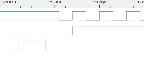
For example if the B button is held down it appears on the first clock cycle, we can see that the data line is low until the clock goes high again.
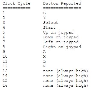
We also have a listing of which clock cycle corresponds to which button is pressed.
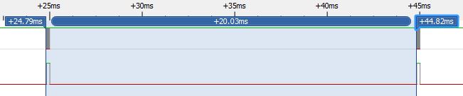
The refresh rate for my PAL SNES appears to be 20ms, for the NSTC SNES it might be 16.67ms.
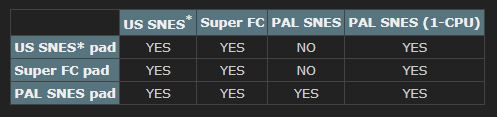
After I opened up my controller I noticed there were 2 resistors, luckily upon my searches for what the pin out was I stumbled across this page about how some of the SNES controllers are region locked but it appears that the PAL controller does work with all SNES consoles as long as those resistors are present, good to know!
We’ve got everything we need so let’s jump to the code, timing will be everything so we’ll run at 16MHz like the Gamecube RX does.
// Wait for latch high from SNES to sync up
while (!(PINB & (1<<LATCH))); // Wait until high
_delay_us(500);

// Turn on pin interrupt on latch pin
PCMSK1 |= (1<<PCINT10);
GIMSK |= (1<<PCIE1);
Firstly we’ll sync up to the controller at the start, once the latch goes high, we’ll wait a little (for the clock cycles to happen) and then turn on the interrupt for the latch pin.
if (PINB & (1<<LATCH)) {
	PORTA |= (1<<DATA);
	while (PINB & (1<<LATCH)); // High, wait for it to go low

	// 16 bits of data to write depending on what keys were pressed
		PORTA &= ~(1<<LED);
	while (PINB & (1<<LATCH)); // High, wait for it to go low

	// 16 bits of data to write depending on what keys were pressed
	for (uint16_t x = 0x8000; x != 0; x >>= 1) { // Loop 8 times
		if (kpOutput & x) {
			PORTA |= (1<<DATA);
		}
		else {
			PORTA &= ~(1<<DATA);
		}

		while (PINA & (1<<CLK));
		while (!(PINA & (1<<CLK)));
	}
	PORTA &= ~(1<<DATA);
In the interrupt handler, we check if the latch is high, wait until the latch is low and then loop the 16 bit variable. The data bit is output while the clock is high, we wait until the clock goes low and wait until it goes high again before setting the next bit.
// Check for key presses
kpOutput = 0xFFFF;
if (kpData & 0x01) { // A
	kpOutput &= ~(1<<7);
}
if (kpData & 0x02) { // B
	kpOutput &= ~(1<<15);
}
...
While we’re not in the interrupt, we’re just listening for new packets and if a button is pressed we change that bit low.
I’ve added 2 hidden options which allows me to play Donkey Kong 2 Country for the most part: (I’ll probably need to add another mapping to switch the R = A on or off at will or map L = A)
– If A is held when powered up, it maps the Gameboy A button to the SNES Y button and the Gameboy B button to the SNES A button
– If R is held when powered up, it maps the GBA R button to the SNES A button
– If L is held when powered up, it maps the GBA L button to the SNES A button
Interestingly when I wired everything up without the 2 pull-up resistors of 1.2K/3K it did seem power up ok however for some reason once the Gameboy cart was turned on, I could see it briefly connect but then the receiver would stop working. I added in the 3K resistor for the latch and then it started to work, so something a bit strange is going on with the latch line if you don’t have that resistor.
Another odd happens with Donkey Kong 2 Country, there is a 400ns or so glitch pulse on the clock line after the 16 clock cycles. It doesn’t affect anything because we are triggering off the latch, I wonder why it’s happening?
I checked out the NES controller while I was at it and it appears to use the same 3 lines, just few clock cycles so it should be possible to re-use the PCB I’m having made to work with the NES, unfortunately I don’t have an NES to test with and they are pretty high priced in Australia.
Download Wireless_GB-GBA_Controller_RX_SNES_v1.0
Part 1
Part 2: Adding RF channel/address configuration and more testing
Part 3: Communicating between carts for 2 Player games
Part 4: Adding a Gamecube Receiver
Part 5: Adding a Super Nintendo Receiver
Part 6: Making the GBA TX Cart


Unrelated to this project, but how is that lipo charger coming along? I really want to buy one… I remember that you were taking a look about using USB-C instead of Micro USB.
Hi Deses, it was released about 2-3 months ago, here’s the link: https://shop.insidegadgets.com/product/gba-reg-charge-v2-0/
I didn’t know! I was expecting some sort of announcement or final update to the series. Hahaha
Purchased! 😀