Posted in Projects on Oct 22nd, 2018
In Part 6, we looked at upgrading the Multi-game feature to allow for mixing GB/GBC games by using a hardware reset on the Gameboy plus we added the ability to switch the CPLD to select MBC3 or 1 mode (MBC5 is the default) when using the loader.
One issue I wasn’t able to solve was why the GBP didn’t seem to work with the multi-game loader (it doesn’t work on the “22 in 1” cart either) so we’re going to have a look at that and also look at possibly making a new larger sized flash cart using 3.3V flash.
When trying to boot a game from the multi-game loader, we just receive a blank Nintendo logo. If I perform a manual hardware reset, it resets it back to the loader menu fine.
if (multiStage == 2'd1 && inputAddress == 4'd6) begin
  multiStage <= 2'd2; // Turn off any more multi-game bank changing
  romBankMulti <= 7'd1;
  romBank <= 7'd1;
  ramBank <= 2'b0;
  resetGB <= 1'b0; // Reset Gameboy
It felt like perhaps the bank to switch to wasn’t being set correctly, so I tried manually setting a bank in the CPLD when we triggered the reset and that worked without any issues. This leads me to believe that the GBP isn’t outputting the data fast enough in order for the CPLD to pick up the bank before it resets.
// Second stage - Check address 0x6000-6FFF for the bank to switch to
if (multiStage == 3'd1 && inputAddress == 4'd6) begin
	romBankMulti <= inputData;
end
// Third stage - Check address 0x7000-7FFF for reset
if (multiStage == 3'd2 && inputAddress == 4'd7) begin
	multiStage <= 3'd3; // Turn off any more multi-game bank changing
	romBank <= 7'd2;
        ramBank <= 2'b0;
        resetGB <= 1'b0; // Reset Gameboy
end
So after playing around for a while, I decided to switch back to executing the commands from the HRAM and adding another stage to the loader to do the reset after the multibank variable is loaded.
(more…)
Read Full Post »
Posted in Projects on Sep 30th, 2018
An idea came to me after looking at some Gameboy projects which swapped out the Gameboy PCB for their own custom board – What if we could use any Gameboy (GB, GBC, GBP, GBA, GBA SP) as a game controller, stream that over a wireless connection and use a V-USB to act as a HID keyboard or joystick. It’s now available for purchase at www.wirelessgbc.com.
It’s do-able I thought, I’ve already played around with all parts that would make this project, I just have to put it all together (and have some code I can re-use): GBDK to make the rom, either a CPLD or MCU to read the input/data, nRF24L01 or similar for the wireless and V-USB on an Atmel MCU for the joystick input. I was considering using Bluetooth as well but might as well just stick with what I know for the moment.
V-USB Joystick Interface
At first I thought about using V-USB just to output keystrokes as I had done this before with the SATVL however I quickly found that outputting and repeating a keystroke like the right cursor key, doesn’t replicate well into an emulator. Basically it’s just like the key is being pressed and released quickly, so if you wanted to move your player right, it would move them right for a little bit, then stop, move right more, etc. I tried playing around with the code but it was a no go.
I went looking to see how other users implemented their own controllers and came across the USB NES Pad adapter that uses the HID joystick interface.
(more…)
Read Full Post »
Posted in Projects on Sep 21st, 2018
In part 4, we looked at adding Multi-game support to our Gameboy cart however I’ve just recently found that we can’t play GBC games using it because the loader runs in Gameboy mode so when we jump back to 0x100 to soft reset, the Gameboy still thinks it’s in Gameboy mode.

Some GBC games like Super Mario Bros. Deluxe come up with a screen saying it can’t be run.

I tried to compare the difference in registers and I/O when starting a game in regular GB mode and GBC mode but apart from the A register and a few others if I changed those registers before trying to boot SMBD but we get some corrupted tiles.

I found that in GBDK you can also program in GBC mode, so I played around with the “Color Bar” example, removed a few parts of it so that I could print text and basically copy the loader code into it. The text looks faded but SMBD boots fine.


But a GB game like Tennis doesn’t look good, something about the palettes aren’t right. If you change register A to 0x01, it doesn’t help much either.
(more…)
Read Full Post »
Posted in Projects on Sep 8th, 2018
From our previous part, we looked at how to add Multi-game support to our cart. In this part, we’re going to switch out the 128KB SRAM for 32KB FRAM so that we no longer need a coin cell battery to keep our saves and also look at adding 2MB MBC1 ROM support; at the moment we are limited to 512KB MBC1 ROM support.

We’ll be using the Cypress 32KB FM18W08 as our FRAM chip which only costs $1-2 each from AliExpress. It has the usual CE, WE, OE lines and address/data lines like an SRAM chip does so it’s almost a drop in replacement.

The one thing that datasheet mentioned compared to SRAM is that the CE line needs to be strobed when you change the address, mainly due to the fact that the memory access needs a pre-charge which is performed when CE goes high for a certain amount of time.
When you read data from the memory cells to the internal buffer, the data from the memory cells is lost until you write it back, this is what the pre-charge is for (odd name for it), it writes the data from internal buffer to back to the memory cells so it’s a good idea to have a pull-up on the CE line (which I do already have). More information on F-RAM pre-charging can be found here.

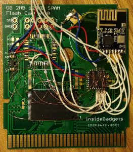
With that out of the way, I built up another Gameboy cart, glued down the FRAM chip and wired it up.
(more…)
Read Full Post »
Posted in Projects on Aug 29th, 2018
From our previous part, the PCBs arrived and I started testing games. There were a few that didn’t work and was able to get some to work by adding some MBC1 support via a few little detection hacks. This part, we’ll look at how to add Multi-game support plus use GBDK to create our game selection screen loader.

(sneak peak of loader screen)
Multi-game support is pretty useful if you have a lot of little games that are 32-256KB but don’t want to have a cart just for each of them. They might also be games that don’t need to save because it can be very easy to load the wrong game and it could potentially overwrite the SRAM.
The way multi-game support works is once you select a game, it send either the bank or the memory location of the game to the custom MBC via an address that wouldn’t likely be written to, the ROM bank is changed, the Gameboy is soft reset and then the game loads.
reg [6:0] romBankMulti;
...
romBankMulti <= 7'd2;
...

// *** ROM Functions ***
if (inputAddress <= 4'd7 && (!inputRD || !inputWR)) begin
	if (inputAddress <= 4'd3) begin // 0x0000-3FFF, Bank 0 always
		highAddress <= romBankMulti << 1;
	end
	else begin
		highAddress <= ((romBank + romBankMulti) << 1);
	end
end
Just to test the concept, we can append one 32KB game to another 32KB game, flash it to the cart and then add a rom bank adjustment variable for multi-carts. If we change the variable to be 2, it will select bank 2 of the flash chip when the Gameboy asks for bank 0. When it asks for bank 1, we simply add the romBankMulti variable to the rom bank the Gameboy asked for; we are always adjusting the rom bank to be 2 banks higher than what it asks for in this case.
Now we just need to make that rom bank adjustment variable configurable so what’s the best address for us to send the bank command to our CPLD? We also need to consider that users may not use the multi-game loader so it shouldn’t conflict with normal cart operation.
(more…)
Read Full Post »
Posted in Projects on Aug 12th, 2018
From our previous part, we added the SRAM and tested the battery backup was working correctly. In this part, I was hoping to look into the FRAM but instead when the PCBs arrived, I started testing games, found a few that didn’t work and was able to get some to work by adding some MBC1 support via a few little detection hacks.
I was laying out the PCB, was almost done, then I looked at an actual cart and realised there was a hole in the board, this screw hole would go straight through the ROM. I didn’t want to re-layout the board having already spent hours on it but happened to notice that some clone carts had the hole at the top. After moving the CPLD a little bit, it worked out fine.

The prototype HASL PCBs arrived a little while later, they sort of fit the cart but I’ll need to move the screw hole down just a tad. At the time, I didn’t have any CR2025 SMD tabbed batteries so I just put in a through-hole coin cell holder. You might also notice that the board is quite thick; I didn’t measure the thickness and left it as 1.6mm when it’s really 0.8mm. Another little issue is that R1/R2 resistors are too close to the bottom of the board, so I’ll move them up. I brought out the clock and audio in lines to the CPLD just in case I ever wanted to play around with those.

Little problems aside, the PCB worked well, loaded up a couple games and played them without any issues so I made the little changes to the PCB and had it done with ENIG, gold fingers with a 45 degree bevel and ordered 50 of them.
Current consumption
I wanted to see how much current the cart was taking compared to other carts so I measured the current of the whole GBA – running Pokemon Silver start screen it was reading 139/141mA while regular carts were 83mA. It’s quite a bit actually but most of it is due to the CPLD (even unprogrammed ones draw 30mA!).
(more…)
Read Full Post »
Posted in Projects on Aug 6th, 2018
In the last part, we looked at 3 DC-DC step down converters, tested their quiescent current and efficiency but none really stood out in both aspects. Near the end, we came up with a solution to which keeps the DC-DC in shutdown and only enables it when the GBA power switch is flicked on. In this part, we’ll continue to test this solution, look at how to detect low battery, order some boards and check the performance.
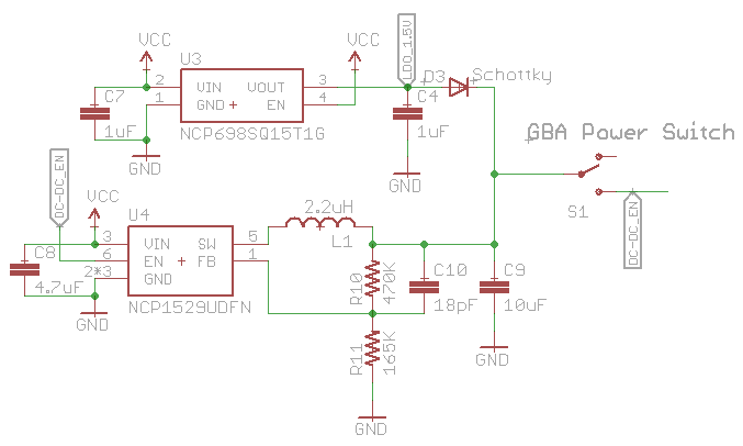
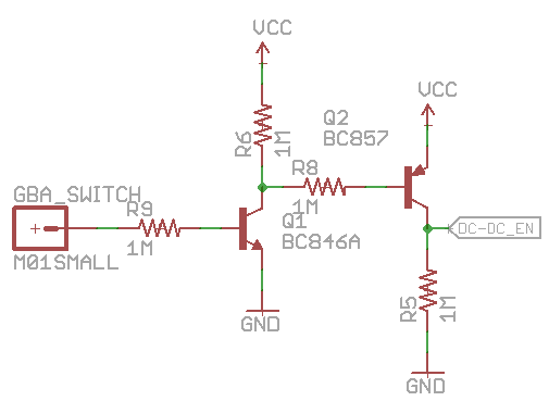
Here’s a schematic to show how the solution works, you can see the LDO’s output goes through the diode and is tied to the DC-DC output. The DC-DC enable pin is tied to the other side of the switch and would normally be off. Once the switch is flicked, the LDO output voltage reaches the DC-DC enable pin and switches the DC-DC on.
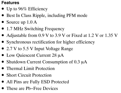
Previously I was using a 1.8V LDO I had laying around for testing so I ordered an ultra low quiescent current LDO, the NCP698 which has a quiescent current of 6uA maximum. The 1.8V version was 20c more expensive than the 1.5V variant so I went with the 1.5V one instead as it should still work fine. We don’t want to have too high of a voltage, otherwise the LDO would be powering the GBA instead of the DC-DC.
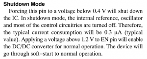
When testing it out, it looked like the output after the diode was 1.33V when the GBA was trying to turn on but the DC-DC wouldn’t turn on, even though the datasheet said the voltage above 1.2V should be enough. I hooked up the LDO voltage to the enable pin directly and it did switch on fine.
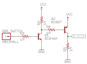
Potentially this could have also happened with the 1.8V variant as well so I wanted to find a way to switch the enable pin to VCC instead of the LDO’s output. After a bit of testing, we can use a NPN with a PNP for our solution, resistors are high value ones so that current consumption is kept low but it only draws current (12uA) when the GBA is on. By default, the NPN is off so the PNP is also off and thus the output is 0. Once the power is flicked on, all we need is at least 0.7V on the NPN so it switches on, the PNP base will then be close to 0V and that will switch on, which means VCC will reach the DC-DC enable pin.
(more…)
Read Full Post »
Posted in Projects on Jul 8th, 2018
Previously I built a GBA LiPo Voltage Regulator & Charger using a op-amp with an NPN transistor to regulate the voltage plus used an off the shelf LiPo charging chip, this is so we could trigger the GBA’s red light when the LiPo was at 3.7V (changed to 3.6V now). The efficiency wasn’t the best (around 62%) and I was lead down this path because I couldn’t find any DC-DC converters with low quiescent current but it turns out that I didn’t search hard enough.
The plan is to use an adjustable DC-DC converter to step down the voltage to around 2.5-3V which should result in higher than 90% efficiency and then use a MCU or similar to toggle a resistor connected to the resistor divider when the LiPo is running low.
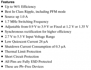
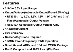
The first 2 candidates for checking the quiescent current is the OnSemi NCP1529 and the Richtek RT8010, both of which switch higher than 1.5MHz, have a 1 amp output and feature a quiescent current of less than 70uA.
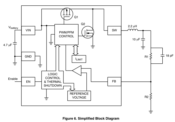
The NCP1529 looked like it might be the best option so I started with that one first. The components to add was a 2.2uH inductor with a 10uF cap, a 4.7uF cap for the input and the the R1/R2 resistor (went with 470K/120K) with a feed forward cap (I haven’t needed to use a feed forward cap before).
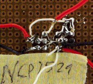
(most of the pictures don’t look too nice, this is because I’ve switch out the inductors, resistors, caps a couple of times!)
Built it all up, powered it up and unfortunately I saw about a 2mA quiescent current. I changed R2 to 220K to adjust the voltage to 1.18V and the current seemed to drop, so perhaps we need larger resistors. I changed R1 to 850K but I was back to 2mA so looks like it’s more the voltage drop that did it. I adjusted the input voltage but it only dropped to 60uA when the input voltage was above 4.8V so that won’t work, it also dropped to 100-200uA when around 3.3V.
I started playing around with it, ended up touching VREF and that’s when the current dropped, weird. So I took out the feed forward capacitor and placed it on VREF to GND and it seemed to work but when I checked it under the scope, it looked bad and under load it was still pretty bad. I added the feed forward capacitor back in and it was back up to 2mA again.
(more…)
Read Full Post »
Posted in Projects on Jun 30th, 2018
From our previous part, we started to configure our CPLD to act as an MBC for which we added support for the 512KB Flash we had on hand, tested it with a 512KB MBC5 ROM which worked. In this part, we’ll switch to the 2MB Flash and add support for SRAM.
// ROM writing (audioIn low), pass through a14-15 OR with romBank
if (!audioIn) begin
	highAddress <= ((romBank & 7'h7C) << 1) | (inputAddress[3] << 2) | (inputAddress[2] << 1);
end
Previously when using the 512KB flash we had to add a different method of programming the flash via the audioIn port as the flash commands being sent would conflict with our A14 & A15 lines controlled by the CPLD.
Now that we have the 2MB AM29F016B flash chip, we can remove all mention of the audioIn line from the CPLD and hook up the flash’s WE line to the WR line. After a quick test with a 2MB ROM, it programmed and read back fine and tested on the GBA fine too.

Over to the SRAM now, the chip I’ve gone with is the Alliance 128KB AS6C1008-55TIN which supports a 2.7V to 5.5V supply with a data retention voltage of 1.5V; there isn’t too many SRAM chips that support up to 5V.

It has the usual CE, OE, WE pins but also a CE2 pin which is kind of strange as it doesn’t actually do anything useful, we’ll just tie it to VCC. I decided that I’ll bring the RD / WR pins to the SRAM and just have the CPLD control the SRAM CE line.
(more…)
Read Full Post »
Posted in Projects on Jun 8th, 2018
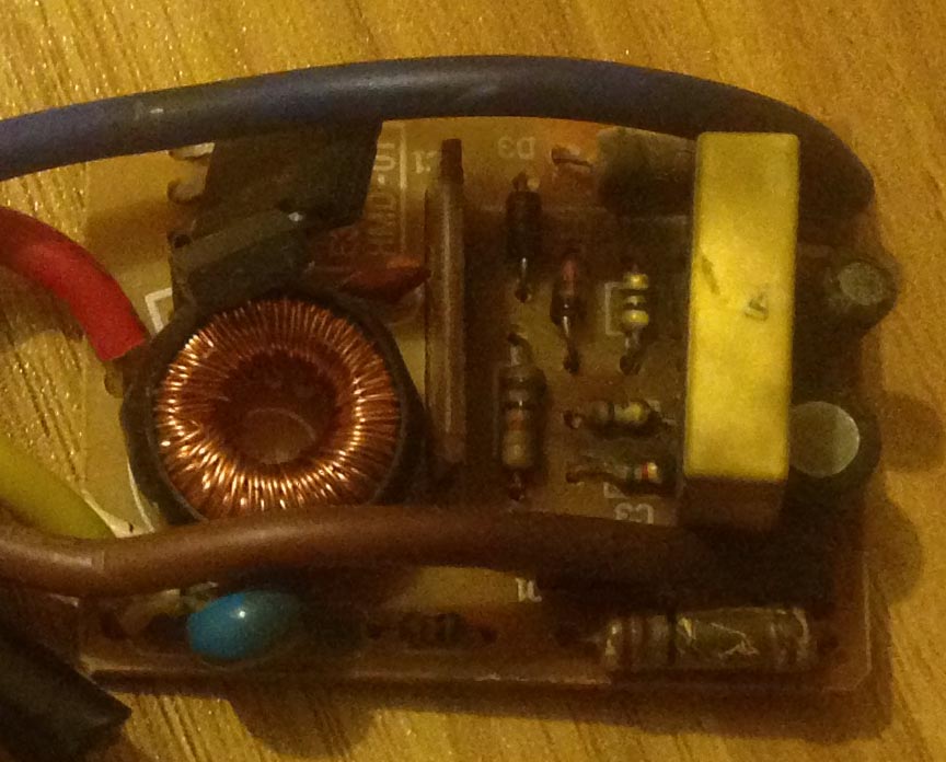
We had a working touch lamp and then all of a sudden it wouldn’t work anymore, it’s happened to a similar lamp, these lamps are probably 10 years+ old, it’s a Mirabella TL007.

After a quick inspection, the circuit board didn’t smell or look too good. We could try to find the fault and repair the board but I thought it might be more interesting to make our own touch lamp with an ATtiny and just re-use the existing lamp base.
I won’t be wiring it up to the mains, instead since I have an alarm clock already running at 5V (with an 3.3V LDO), I can just wire up directly to the 5V source. The LED will just be one of those 1/2W LEDs you can pick up off Ebay for $1-2 so we’ll just need some dropper resistors or if you wanted to, you could make or buy a constant current driver.
For the touch sensing, you can buy a chip to do that (or it could be integrated already to an MCU you choose) or do it by hand, of course I went with the by hand method as I’ll be using an ATtiny13A. Once touch is detected, we’ll just turn on a mosfet to power on the LED.
To start off, we can use the ADC on a pin to look for any voltage fluctuation but we can’t just leave the pin floating, the pull down resistor needs to be high enough that the pin won’t float, can’t be too low or it won’t detect when we touch it, for me that ended up being 4.7M ohms.
(more…)
Read Full Post »