I’ve recently started to replay some Gameboy games on my Gameboy Colour, I picked up a Gameboy Advance and eventually got around to doing the AGS101 mod to it which makes it look really nice. Eventually I got to the point where I would have to keep recharging the AA batteries I was using as they weren’t lasting as long and the weight of the 2x AA 2000mAh rechargeable batteries made the GBA feel a bit heavy.
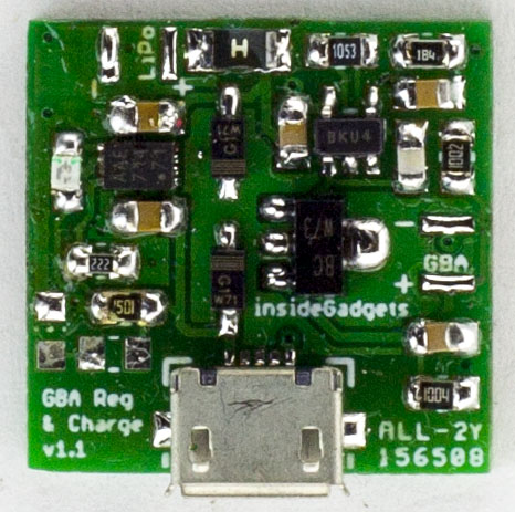
I saw a post where someone fitted a 2000mAh LiPo battery to their GBA, they had do to some modifications to the GBA battery compartment to fit it all. By using a LiPo battery instead of the AA’s, it would save us about 20 grams, while not a lot, ever gram does count and you can tell the difference plus since the LiPo has a higher voltage, it has a higher energy density, so it should give us longer play time than the AA’s. So I decided I would do the same mod and I might make a little voltage regulator and charging board to go along with it.
We can’t just directly hook up the LiPo battery to the GBA, you have to step it down to around 3V. You could go higher but I chose not to as who knows what that might affect seeing as the the GBA has a DC-DC boost converter on board stepping it up to 3.3V/5V.
A DC-DC buck converter could do the job to reduce it to 3V and so could an LDO but from my experiences, both of these options seemed to have quite a high quiescent current (usually around 1mA), we would waste power even when the GBA was powered off. One way around this would be to keep the device in shutdown but then how would you detect if the GBA was powered on?
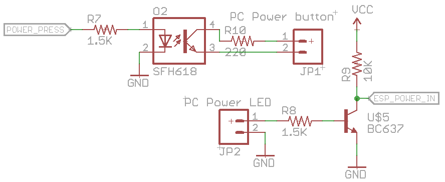
I know this sort of project has been done before but nevertheless it’s still an interesting project to try and put your own spin on it. The idea is to have an ESP8266 which can press/hold the power button and might as well have it also read the power LED state, you could also wire up the reset button if you wanted to, it’s a good concept for servers (or PCs) which don’t have a remote management and you need something basic.
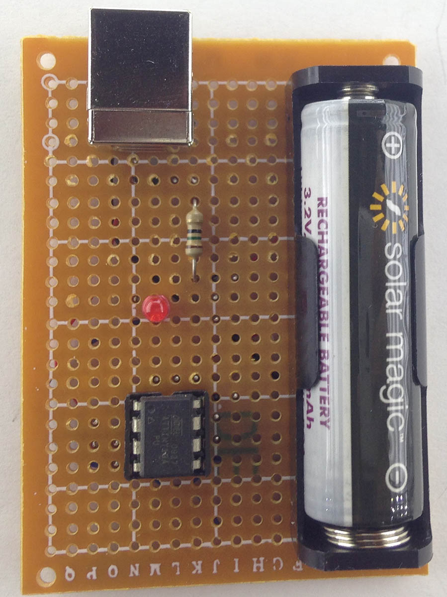
(sneak peak of prototype)
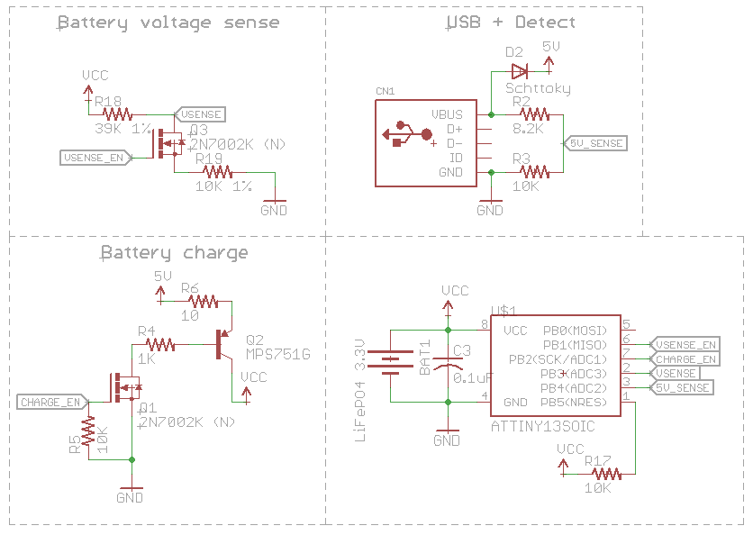
One option might be using the 5V standby power which most power supplies provide when the PC is off. Some PCs might have 5V standby available in the BIOS, the keyboard and mouse might stay on, maybe you could find some pins on the mainboard but perhaps some mainboards might not have it? Let’s just avoid it all, I’m thinking I could have the ESP8266 powered off a 3.3V LiFePo4 battery in a small little case which when the PC is on, it will recharge itself via USB, this way we don’t need the PC to be on or have the ESP8266 powered via a mains adapter.
For the circuit, we can sense the power LED, it will have a voltage drop out say 2-3V with the LED but could have 5V if the LED isn’t connected for whatever reason, we’ll just use a NPN to switch 3.3V on or off to our input pin. The power switch we can use an opto-isolator to turn it on or off which can be inline with the power button. We can also integrate the USB LiFePO4 charger into this project to charge the battery.
That’s pretty much all there is to the hardware, now for the software which is where it’s all at. We want to make it as simple as possible to setup without needing any port forwarding on the client’s end, so the design is to have the ESP8266 reach out to a server to fetch a command over HTTPs. We don’t want the ESP8266 to be awake all the time otherwise the battery won’t last long so we’ll utilise the deep sleep function and say wake up once every 5-10 minutes.
I’ve built a 32KB Gameboy cartridge before to add support for certain flash chips to GBxCart RW but those were wired straight through without the need of an MBC so I thought it might be interesting to jump back into CPLDs by building an 2MB Gameboy cart.
We have a few options when building a Gameboy cart, use 5V Flash chips (which are pretty rare these days) with 5V SRAM chips or go 3.3V Flash/SRAM chips and use level shift transceiver with direction control to interface with the Gameboy’s 5V logic. Because this is my first real cart, I’m going with easier the 5V flash/SRAM chip option for the moment.
(sneak peak of the cart running a game)
The only flash chip I have on hand is the 512KB AT49F040 so I’ll use that at the start and then we’ll transition to the 2MB AM29F016B in a later part once it arrives. For the MBC, I have an Altera EPM3032 CPLD handy so we’ll go with that, it runs off 3.3V so we’ll need an LDO for it and the inputs accept 5V logic.
Initial Planning
Let’s get started, firstly we’ll review the MBC5 documentation to determine which addresses the CPLD will need to read for changing ROM banks/RAM banks, etc. The lowest address is 0x0000 – 0x1FFF for RAM enable, the highest bit of that address that’s a 1 is A12 so that’s where we will start. The highest address is 0xBFFF when accessing the RAM, so A15 is where we will end, that makes 4 bits which are needed for listening to incoming MBC requests.
Since I’m starting to use more LiFePO4 14500 batteries I thought it would be a good idea to build a simple USB charger for them instead of having to charge 2 at a time on the xxx battery charger. The most simplest way would be to stick it on a CV/CC power supply or another way is to stick it on a CV power supply set to 3.6V with say a 1 ohm resistor and wait for it to reach 3.6V, not the quickest to charge but it works.
My first design was to use a voltage reference such as a TL1431M (or a resistor & zener diode) set to 3.3V with a decent op-amp like the MCP6242 with hysteresis threshold set to 3.2V – 3.6V and an PNP transistor to switch the 5V through say a 10-20 ohm resistor to the battery. This would only charge the battery if it was under 3.2V, stop at 3.6V and won’t start charging again until the battery dropped back to 3.2V which it shouldn’t.
It works one problem arises when you unplug the USB side and leave the battery in, it would start discharging a few mA due to being connected to the op-amps output but it’s not like that would really ever happen. But let’s put in an MCU, say an ATtiny13A to sort it out. I have plans to make a device in the future run off the LiFePO4 battery and recharge itself when the USB cable is connected if it matches the threshold voltages as before.
From our previous part, we designed a client with the nRF24 which communicates the LiPo battery cell voltages to a server running from an ESP8266 so we could easily jump onto it and check the cell voltages. In this part we’ll add in email alerts with adjustable battery voltage thresholds, add an easy server setup process to join your Wifi and give the system a test.
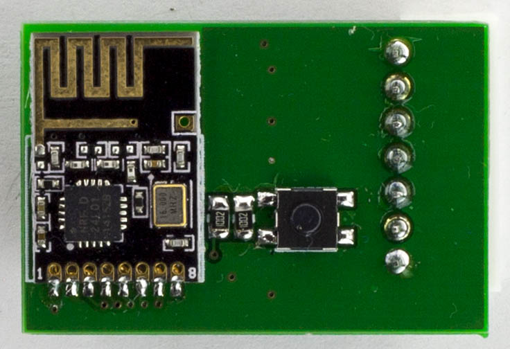
First things first, the client PCBs arrived (34 x 23mm), built one up and it worked well. I sprayed the board with PCB lacquer and put clear heat shrink over it. When trying to link it up to the server, it wasn’t working, seemed to just stay waiting to receive the packet from the server. I eventually found out that I had to bump the voltage up to at least 3.9V for it to link up properly, I’m guessing the 3 diodes dropping the voltage down is part of the issue when listening as it can take quite a bit of current. Sending a packet when it checks in works fine at lower voltages. When ATtiny and nRF24 are sleeping, it takes about 6uA so I’m happy with that.
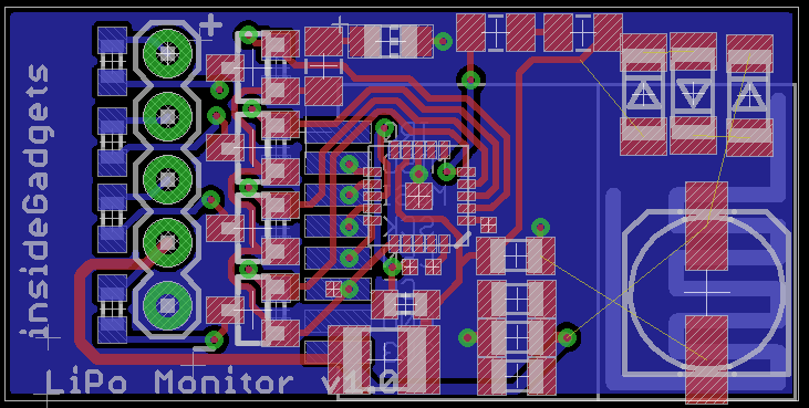
I was thinking about redesigning the board to make it even smaller (32 x 16mm) if you just had up to a 4 cell battery, it would be a little bit harder to build.
From the previous part, we designed a small power supply based on a Richtek DC-DC, added an 128X64 OLED display and gave it a quick test which it seemed to cover most voltage ranges with better increments than the old SPPS.
(sneak peak)
The PCB’s arrived and we’re ready to start populating each segment individually to make sure each part works. I put on the ATmega328 with the LCD, tested ok. Next was the main DC-DC converter with digital potentiometer and to test controlling it from the ATmega which seemed to work fine. One thing I hadn’t really paid attention to was that the DC-DC converter only goes up to supply voltage – 2V or so from my testing, the reference voltage starts to drop from the nominal 0.8V and it started to oscillate, so I might need a 18V power supply if I want up to 15V output.
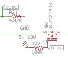
Output Enable troubles
Next I soldered the P mosfet for the enable so I could enable or disable the output, that’s where things didn’t go as planned. I hadn’t considered the case where the power supply was set 2V and the gate was low, Vgs would only be -2V which is not enough to turn on the mosfet, you need something like -5V or higher to full switch it on, basically under 5V it was unusable, the mosfet would be dropping most of the voltage.
Wouldn’t it be nice to know it you have mail? I think it’s a good idea and had it on my to do list for a while. Our letterbox looks similar to the one above, you can place small items on the top, in the letter slot or open it up from the back.
At first I thought we could do this with a vibration switch however upon testing the switch it looks like it needs a fast motion in order to activate. Another option is a reed switch on the top part so if the mailbox is opened, it will detect that, but would leave letters undetected. And yet another option, is a light sensor placed inside the mailbox but also results in the same problem.
So one of our last options is to use an accelerometer to detect the slightest touch of the mailbox, most mailboxes are pretty rigid but ours has a tiny bit of moment to it, we can’t really put the device we would make in the letterbox itself as the RF would mostly be blocked so it would have to be placed outside. As usual, I’ll be using an ATtiny84 with the nRF24 to simply send a packet when the interrupt occurs.
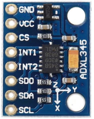
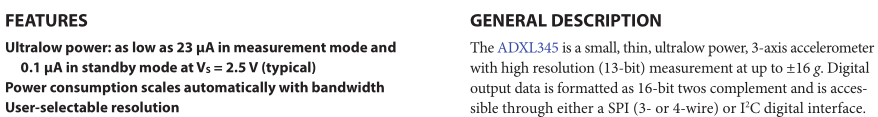
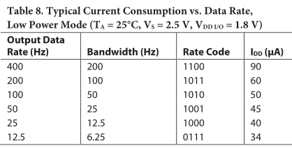
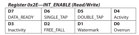
The accelerometer I’m looking at as you can tell by the title is the ADXL345 which has 2 interrupts available for single tap, double tap, activity, etc, and current consumption looks to be pretty low. It supports I2C or SPI, we’ll be using 4-wire SPI.
So I tried the SparkFun ADXL345 example which worked well, they have all the interrupts available so all I need to do is take everything I don’t need out, convert it to C and try out the low power modes. Note that the ADXL345 is a 3.3V device so you will need a logic level converter if using it with a 5V Arduino.
I have a couple of nRF24 devices around the house like the doorbell, front door camera, the single receiver for both and I might look to expand that list in the future but re-programming the receiver when you would like it to handle a new device or perform an additional action can take a while plus the time testing that everything works.
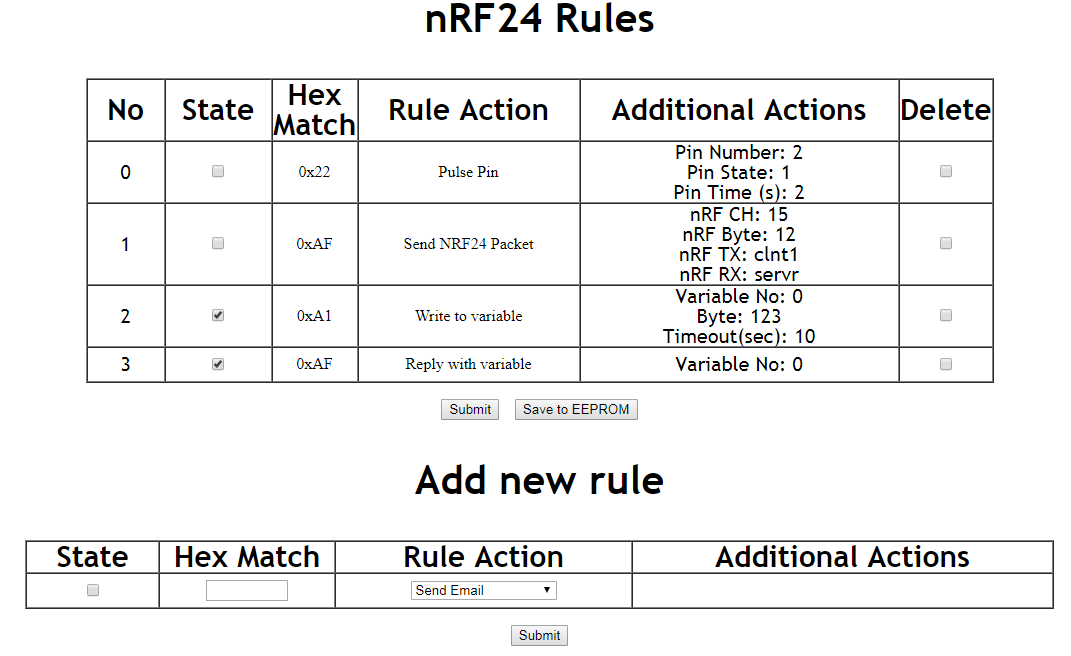
So I thought, why not make an ESP8266 for a web interface where we can store rules and have it connected to the nRF24 to receive incoming packets, it’s similar to IFTTT but all local. The rules would all be based on a single byte packet it would receive, we could have the rules active or not, with rule actions such as sending an email, pulsing a pin for a certain amount of time, sending an nRF packet, writing data to a common variable (with a timeout when it’s reset) and reply back with that variable. We can have a button to save everything to the EEPROM (emulated on flash) and read it all back if the ESP8266 is power cycled.
Some quick use cases:
– Doorbell is pressed, you could either have it pulse the buzzer locally for a second or two and you could also have a remote buzzer anywhere else so it sends a packet to have that buzzer go off too.
– I’m thinking about adding a small sensor to the mailbox, so if it’s moved, it would send a packet, we could have it write data to a variable. Add a battery powered sensor anywhere around the house with either a buzzer or LED, to check in every few seconds and read that variable back so if it changes to a 1, the buzzer or LED goes off for a little while.
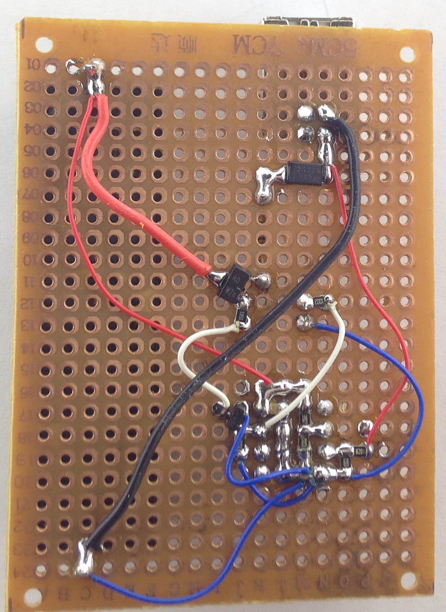
When finding out that one cell of my 3x 4S 1300mAh batteries were discharged to 3.3-3.4V (other cells were 3.7-3.8V) after not flying for 2-3 months, I was a bit surprised, these batteries were one of my first batteries purchased about 1.2 years ago. I’ve tried to be better now, checking packs every month, I’ve got some old packs for the RC car that hardly get used so I wrote down the idea to do battery storage voltage monitoring a few months ago so let’s make it happen.
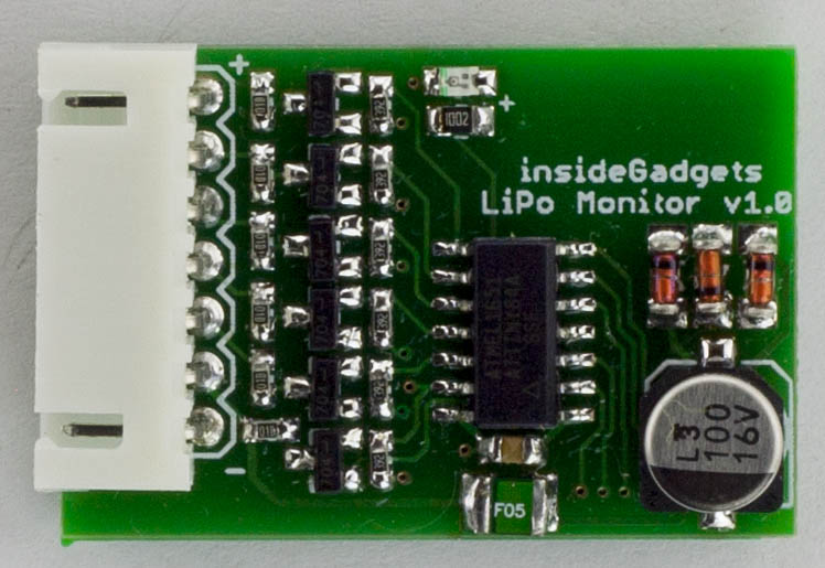
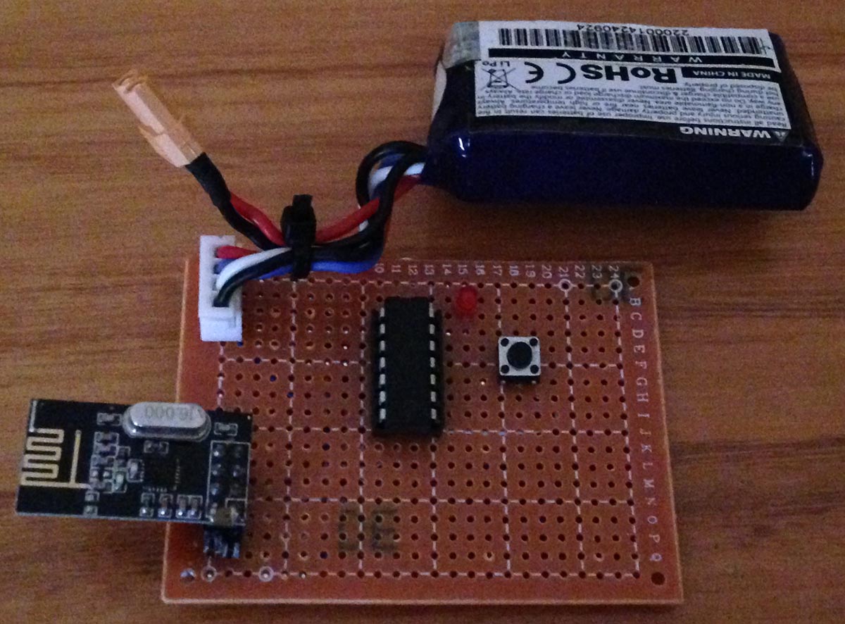
I’m thinking of using the nRF24L01 module (as it’s pretty low cost), using an ATtiny24/44/84 which should give us 6S support and have it powered from the first cell of the LiPo, it shouldn’t take too much current from the first cell as we stay in sleep/power down most of the time. Add in a few resistors, led, mosfets to turn on when we want to measure the voltage. I will coat the PCB in lacquer and cover it with heat shrink to protect against the environment and since the board needs to be as small as possible, I’m going to try the SMD version of the nRF24.
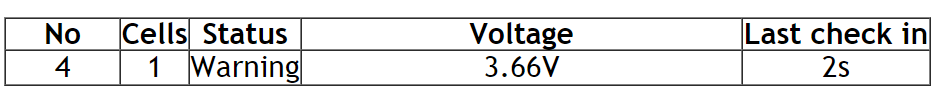
Check-in times for these sensors might be in the range of hours as battery voltage won’t change too much, it would be nice to have a graph over say 30 days but I might look into that later if I feel it’s worth doing, for the moment it will just show the sensor number, cells, status if it’s ok or not, battery cell voltages and last check in time. Server side would just be an ESP8266 with the nRF24L01 directly attached so no need for any other MCUs.
Previously I was looking at making a Dual Output Linear Power Supply, the prototype was working but while designing the PCB it would end up being large, a bit heavy with the heat sinks and I don’t think I would really need a linear power supply, it was a nice idea.
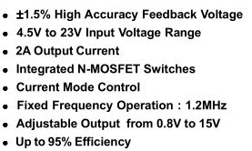
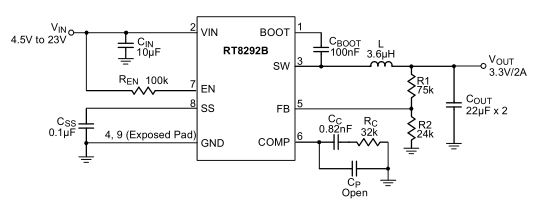
So it’s back to the drawing board as to what I really need, I do still have the SPPS which works but maybe it’s time for an upgrade and now that I know a bit more about DC-DC converters we can stick in the Richtek DC-DC chip instead of using an Ebay DC-DC module. We might as well switch out the 8 digit LED display for an 0.96″ 128X64 OLED SSD1306 display which I’ve seen a lot of projects move to.
The DC-DC converter I’m looking at using is the RT8292B which runs at 1.2MHz versus the 400KHz of the RT8293A which I was using previously, it looks to be almost identical except that it will allow us to use a smaller inductor.
Like we’ve done before, we will use a 10K resistor for R1 and 10K digital potentiometer for R2 to control the output of the DC-DC.
AdvanceVGA – Play your GBA on the big screen! Swap out the LCD for our board, solder some wires, connect 5V USB and VGA and you’re ready to go.
GBxCart RW allows you to backup GB/GBC/GBA ROMs, save or restore game saves and re-write supported flash carts. Mini RW option available for GB/GBC only.
Wireless Gameboy Controller – Use your Gameboy, mGB, GBC, GBA, GBA SP, GB Micro, NDS and NDS Lite as a wireless controller on Windows, Linux, Raspberry Pi, etc, and on your NES, SNES, N64, Gamecube and Wii.