Following on from Part 2, we added a rotary encoder and performed more testing in which we found that since we’re using an LDO (a type of linear regulator), that the mosfet is dissipating the voltage drop, something which I forgot about.
I checked out the LM2596 module again as I was testing designs of making a switch mode regulator like it. On closer examination of it, I found a feedback resistor which I didn’t notice before (next to the 10K por). When removing that resistor I found that re-adding the digital pot this time with a high side resistor of 4.4K allowed me to have a voltage range of 1.8V to 12V however it’s still the case when at the lower voltages it takes more turns of the encoder to increase the voltage, at the higher end the reverse happens but it’s still workable.
Another solution is to use the LM2596 as a pre-tracking regulator as someone mentioned in the comments, so it would absorb most of the voltage drop and then we’d have the mosfet with the op-amp as before – maybe I’ll implement this for the next version.
// Check if reading minus previous reading is 0.1V difference
if (dpotValue < 255 && ((calculateDouble - previousReading) > 0.1)) {
  buttonLeds = LED3;
  _delay_ms(250);
  previousReading = calculateDouble;
  stepIndex[currentStep][DPOTVAL] = dpotValue;
  stepIndex[currentStep][ADCVAL] = adcValue / 3;
  currentStep++;
}
else if (dpotValue == 255) { // No more to go, finished
  stepIndex[currentStep][DPOTVAL] = dpotValue; // Add top value
  stepIndex[currentStep][ADCVAL] = adcValue / 3;
  currentStep++;

  calibratingDpot = false;
  calibratedDpot = true;
  _delay_ms(1000);

  // Store in EEPROM
  eeprom_write_byte((uint8_t*) NO_OF_STEPS_LOCATION, currentStep);
  int y = STEPS_START_LOCATION;
  for (int x = 0; x < currentStep; x++) {
    eeprom_write_byte((uint8_t*) y++, stepIndex[x][DPOTVAL]);
    eeprom_write_byte((uint8_t*) y++, stepIndex[x][ADCVAL]);
  }
  currentStep = 0;
}
else { // Increase voltage
  dpotValue++;
  buttonLeds = 0;
}
I’ve now switched to the 8bit 10K digital pot. Since the digital pot takes more steps to increase voltages at the lower end, we can make a calibration option in which we set the digital pot to 0 and then increase it until we see a change in 0.1V on the ADC. Once the calibration is completed, we save this to the EEPROM and then load it again on boot. You can also reset the calibration if you don’t want it to jump up or down in 0.1V steps. At higher voltages, it’s more like 0.5 – 0.8V steps but that’s not too much of a concern for me.
https://www.youtube.com/watch?v=0YiXzQDiQKY
The LED blinks every 0.1V increase which is stored in memory. Once the voltage increases to a certain point, the steps become higher than 0.1V.
Download SPPS_v0.3
Extra – Calibration if using the original mosfet / op-amp design
Previously I mentioned how we could do calibration of the voltage which is shown on the LED segments because at the moment we’re just using a formula to get a “close enough” accuracy with a 1M / 39K resistor divider when using the ADC: adcValue * 1.074 * 0.026631 (when at 3.3V). The ATtiny and DAC would be powered by a 3.3V 1% regulator which means the voltage can be between 3.267V to 3.333V.
If our regulator was spot on 3.3V, if the voltage before the resistor divider was 11V, it would be 412mV after the divider and assuming a perfect ADC / resistors / temperature, we’d get 413mV x 0.026631 = 10.998V estimated which is almost spot on. Now if the regulator voltage was really 3.267V, we’d end up with 10.89V with 409mV and an estimated of 10.89V which is once again spot on, so a change in regulator voltage doesn’t affect it.
Now what happens when we change the ATtiny chip, when I measured the 3.3V regulator on the first ATtiny chip I get it jumping around 3.24 to 3.27V whilst on another ATtiny I get 3.27V to 3.3V, so the ADC could be up to 2 counts out. If that was the worst case scenario, the 10.89V would be read as 407mV and we’d get 10.83V so a 50-60mV difference in voltage compared to 10.89V, not too bad.
What if our resistors were only 1%? This could mean that the 1M could be 1.01M, the 39K could be 38.6K and so on but lets just say that the 39K resistor is the only one out at 38.6K. This means that instead of 409mV for 10.89V, we’d get 404mV to give 10.75V = 131mV difference. Now imagine if all resistors were at the worst of their tolerances (very rare) or imagine a combination of the above issues (more likely), you could probably be 200mV or so out.
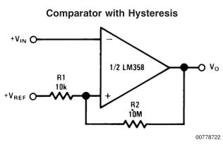
So now we’ll add in an DAC instead of the 10K pot and use the second half of our op-amp as a comparator. Usually you don’t want to use an 0p-amp as a comparator however the reference design from the LM358 seemed to work when I tested it.
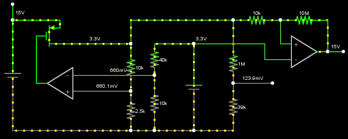
Here’s how it would work, since the regulator gives a 1% accuracy we can use that as the negative side of the op-amp and when the positive side reaches 3.3V, the output goes high. Using a 12 bit DAC allows us to fine tune the voltage on the first op-amp and as long as the 10k / 2.5k voltage divider stays within 1%, we can have around under 50mV accuracy.
When the second op-amp’s output goes high, that’s when we can make a note of ratio between output voltage and the DAC so at 3.3V / 660mV or 3.3V / 819 (estimated DAC value 660 / (3.3 / 4096)), so it’s either x5 or 0.0040293 assuming the DAC is near perfect. Now it doesn’t matter how much offset our ADC from the actual result so long as it keeps that offset all the time (assuming no temperature changes), we can map the 819 DAC value to the ADC’s 124mV to give 6.6048 which we can now use to predict the output voltage.
For example, if our ADC read 435mV we’d do: 435 x 6.6048 = 2873DAC value x 0.0040293 ratio = 11.576V on the output (estimated) which is close to the 11.59V on the simulation. I might build this anyway to see how all this works out, maybe there’s a better way to do calibration?
Part 1
Part 2: Added rotary encoder and more testing
Part 3: Back to the LM2596 and calibration
PCBs arrived
Small Programmable Power Supply v1.0 Released


