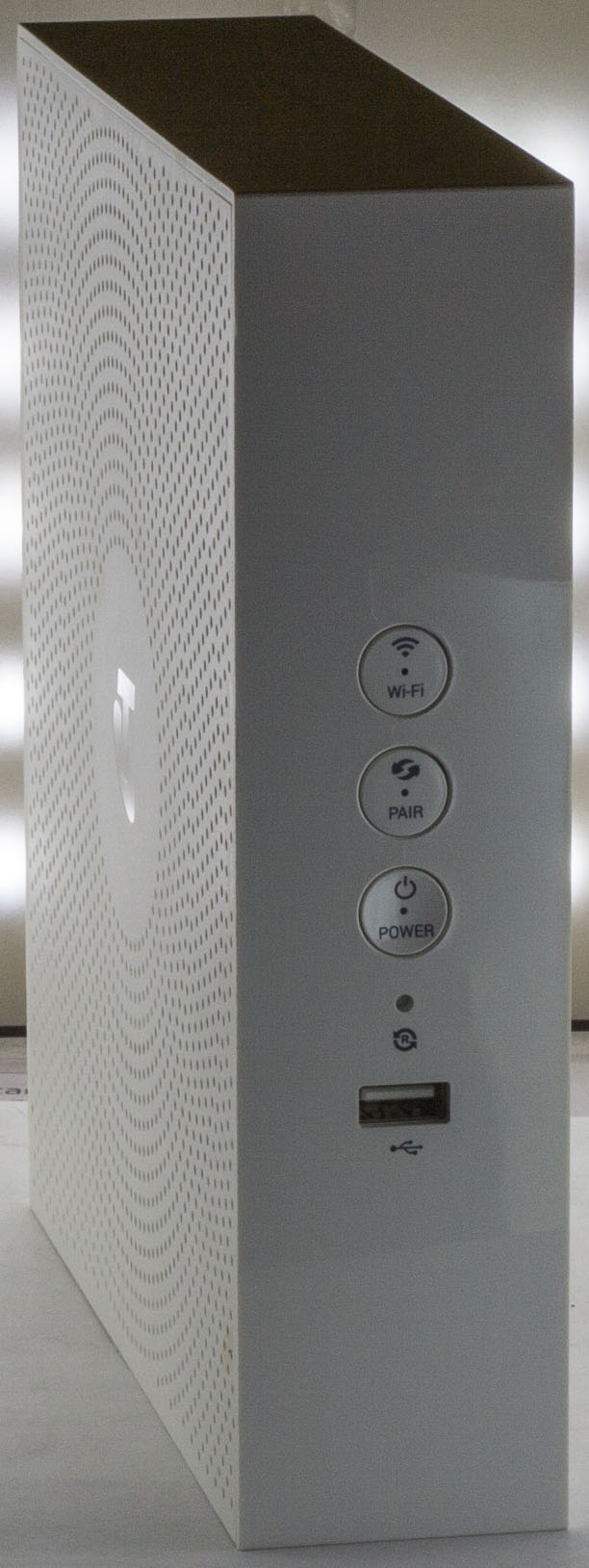
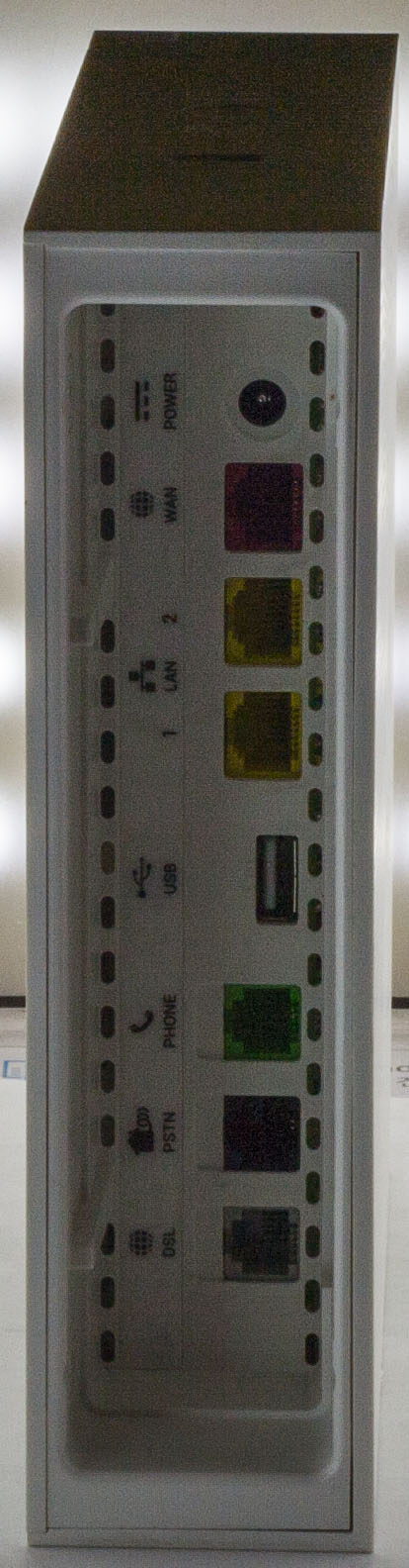
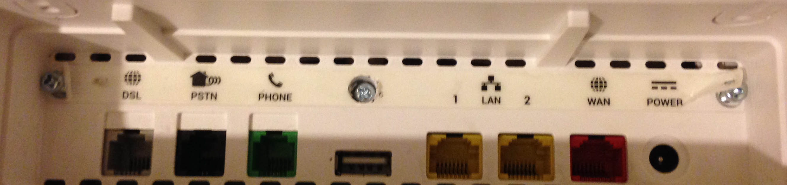
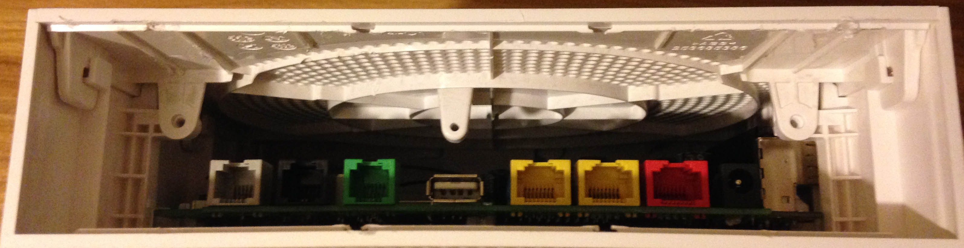
Today we’ll be taking a look at the Telstra F@st 5355 Wifi Router which supports ADSL2+/VDSL2+ on the DSL port, Gigabit WAN port, PSTN and Phone port, 2x 100Mbit LAN ports, 2x USB 2.0 ports, 802.11ac/802.11n Wifi and DECT.
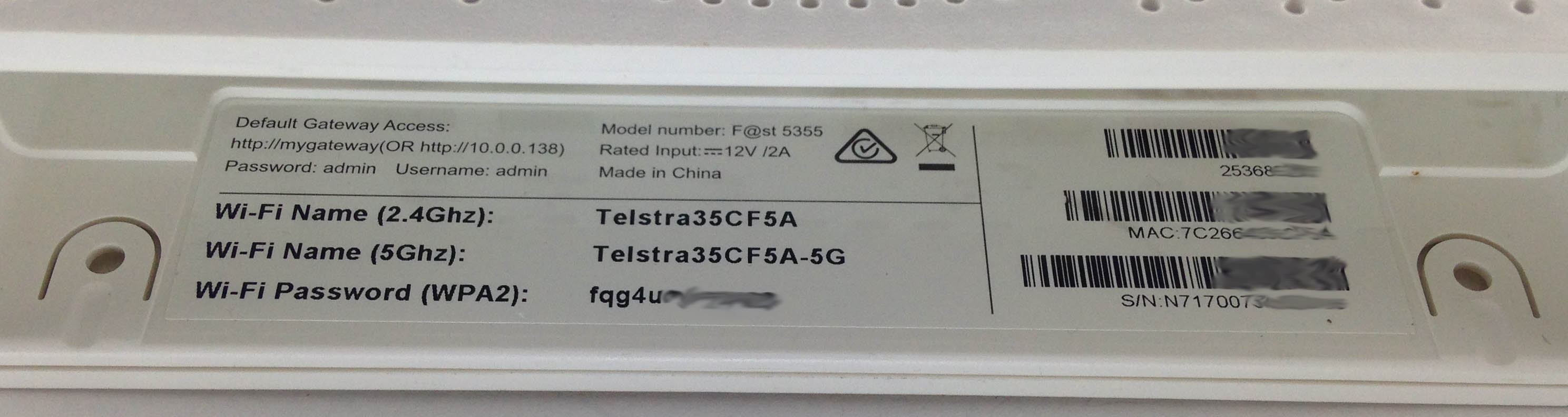
I was trying to look for some screws but couldn’t find any at first until I eventually found there were 3 under the label.
The shell comes out and then you can slide the top off the case.
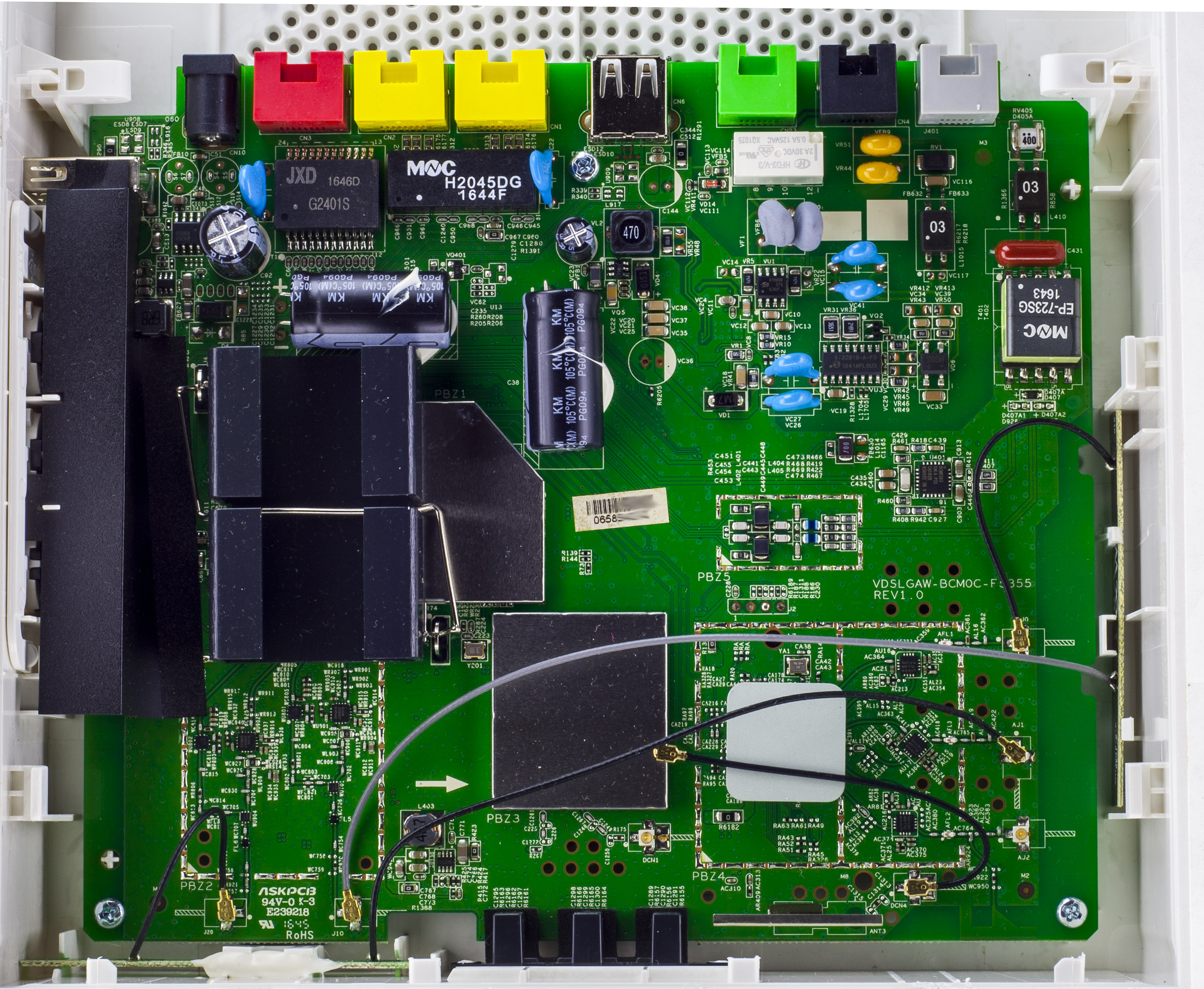
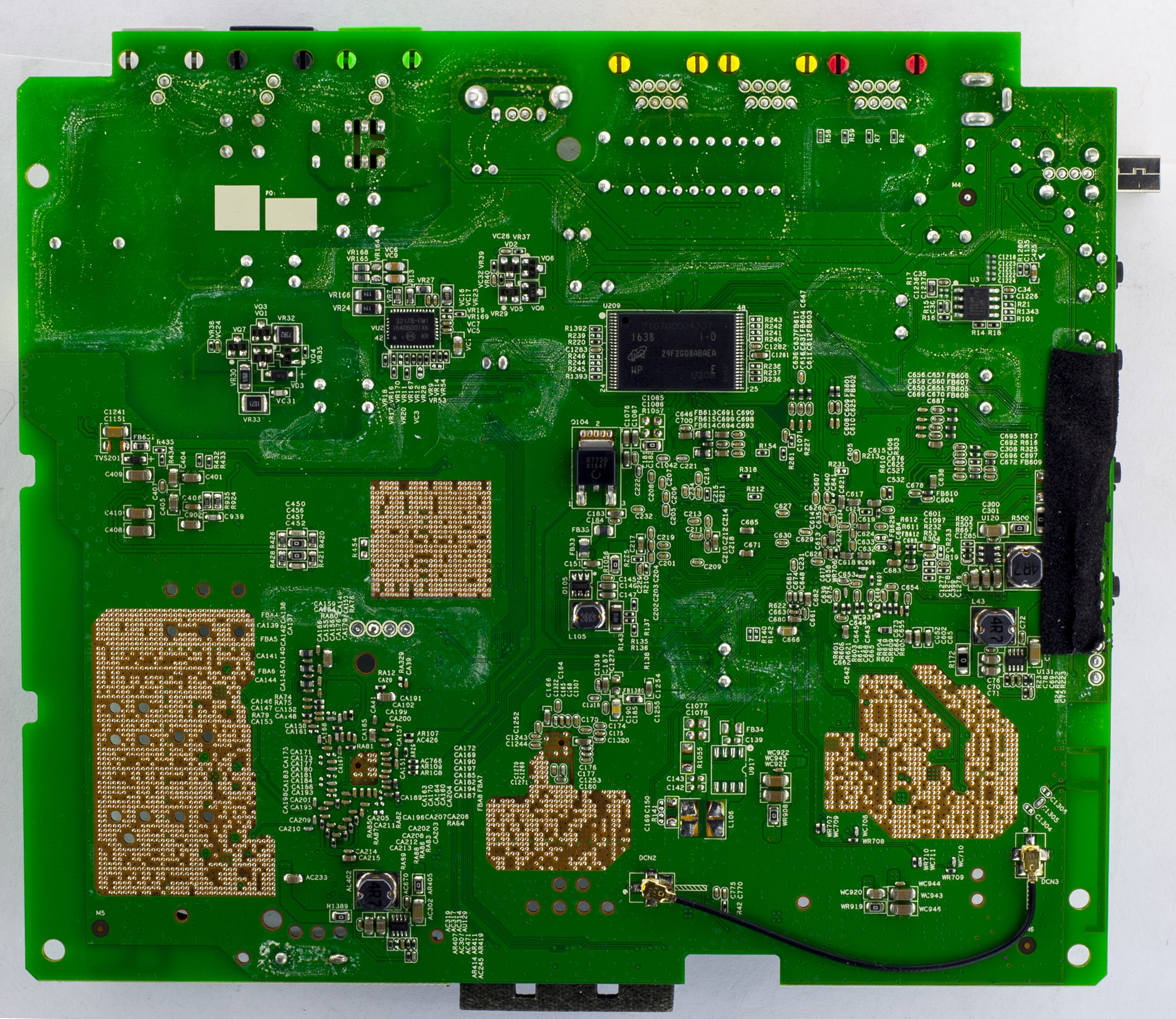
There’s a lot going on, we have a interesting large looking heatsink with a smaller ceramic one, a couple of RF cans, lots of antennas, two large 3300uF capacitors glued down and even more interesting, the back of the board with the exposed pads with it’s via’s looks pretty neat. PCB date code is 45th week of 2016.
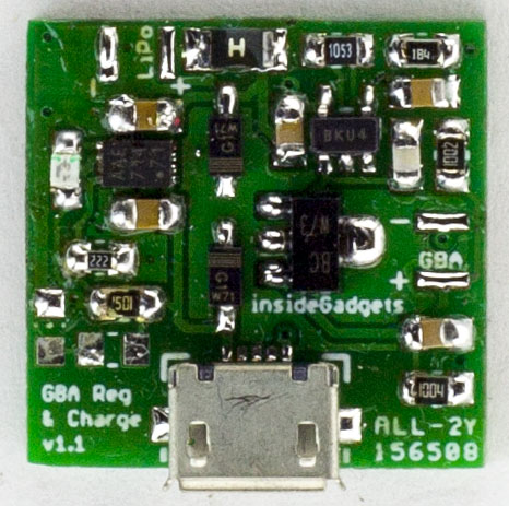
Previously I built a GBA LiPo Voltage Regulator & Charger using a op-amp with an NPN transistor to regulate the voltage plus used an off the shelf LiPo charging chip, this is so we could trigger the GBA’s red light when the LiPo was at 3.7V (changed to 3.6V now). The efficiency wasn’t the best (around 62%) and I was lead down this path because I couldn’t find any DC-DC converters with low quiescent current but it turns out that I didn’t search hard enough.
The plan is to use an adjustable DC-DC converter to step down the voltage to around 2.5-3V which should result in higher than 90% efficiency and then use a MCU or similar to toggle a resistor connected to the resistor divider when the LiPo is running low.
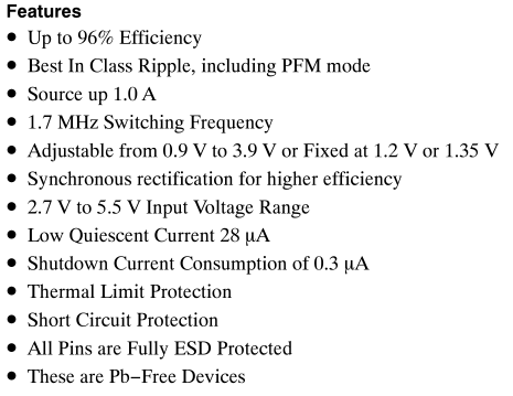
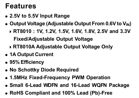
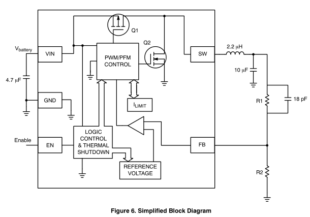
The first 2 candidates for checking the quiescent current is the OnSemi NCP1529 and the Richtek RT8010, both of which switch higher than 1.5MHz, have a 1 amp output and feature a quiescent current of less than 70uA.
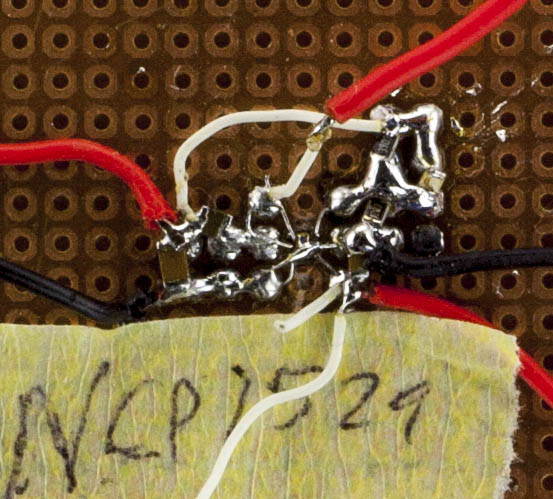
The NCP1529 looked like it might be the best option so I started with that one first. The components to add was a 2.2uH inductor with a 10uF cap, a 4.7uF cap for the input and the the R1/R2 resistor (went with 470K/120K) with a feed forward cap (I haven’t needed to use a feed forward cap before).
(most of the pictures don’t look too nice, this is because I’ve switch out the inductors, resistors, caps a couple of times!)
Built it all up, powered it up and unfortunately I saw about a 2mA quiescent current. I changed R2 to 220K to adjust the voltage to 1.18V and the current seemed to drop, so perhaps we need larger resistors. I changed R1 to 850K but I was back to 2mA so looks like it’s more the voltage drop that did it. I adjusted the input voltage but it only dropped to 60uA when the input voltage was above 4.8V so that won’t work, it also dropped to 100-200uA when around 3.3V.
I started playing around with it, ended up touching VREF and that’s when the current dropped, weird. So I took out the feed forward capacitor and placed it on VREF to GND and it seemed to work but when I checked it under the scope, it looked bad and under load it was still pretty bad. I added the feed forward capacitor back in and it was back up to 2mA again.
From our previous part, we started to configure our CPLD to act as an MBC for which we added support for the 512KB Flash we had on hand, tested it with a 512KB MBC5 ROM which worked. In this part, we’ll switch to the 2MB Flash and add support for SRAM.
// ROM writing (audioIn low), pass through a14-15 OR with romBank
if (!audioIn) begin
	highAddress <= ((romBank & 7'h7C) << 1) | (inputAddress[3] << 2) | (inputAddress[2] << 1);
end
Previously when using the 512KB flash we had to add a different method of programming the flash via the audioIn port as the flash commands being sent would conflict with our A14 & A15 lines controlled by the CPLD.
Now that we have the 2MB AM29F016B flash chip, we can remove all mention of the audioIn line from the CPLD and hook up the flash’s WE line to the WR line. After a quick test with a 2MB ROM, it programmed and read back fine and tested on the GBA fine too.
Over to the SRAM now, the chip I’ve gone with is the Alliance 128KB AS6C1008-55TIN which supports a 2.7V to 5.5V supply with a data retention voltage of 1.5V; there isn’t too many SRAM chips that support up to 5V.
It has the usual CE, OE, WE pins but also a CE2 pin which is kind of strange as it doesn’t actually do anything useful, we’ll just tie it to VCC. I decided that I’ll bring the RD / WR pins to the SRAM and just have the CPLD control the SRAM CE line.
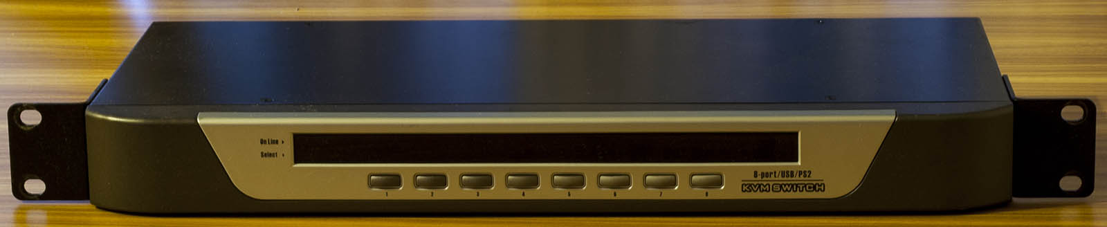
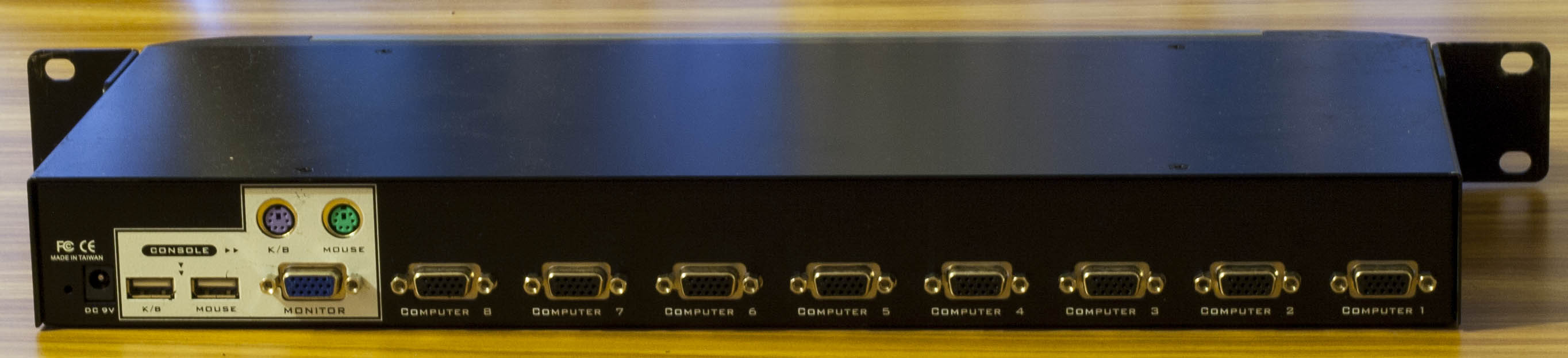
Today we’ll be taking a look at a Generic 8 Port USB/PS2 KVM Switch which has 8 ports which you can switch to with 2x USB/PS2 inputs and a monitor output. There are no markings on the vendor on the outside of the box.
After a few screws we’re in.
(Picture might look a little distorted due to Pano stitching)
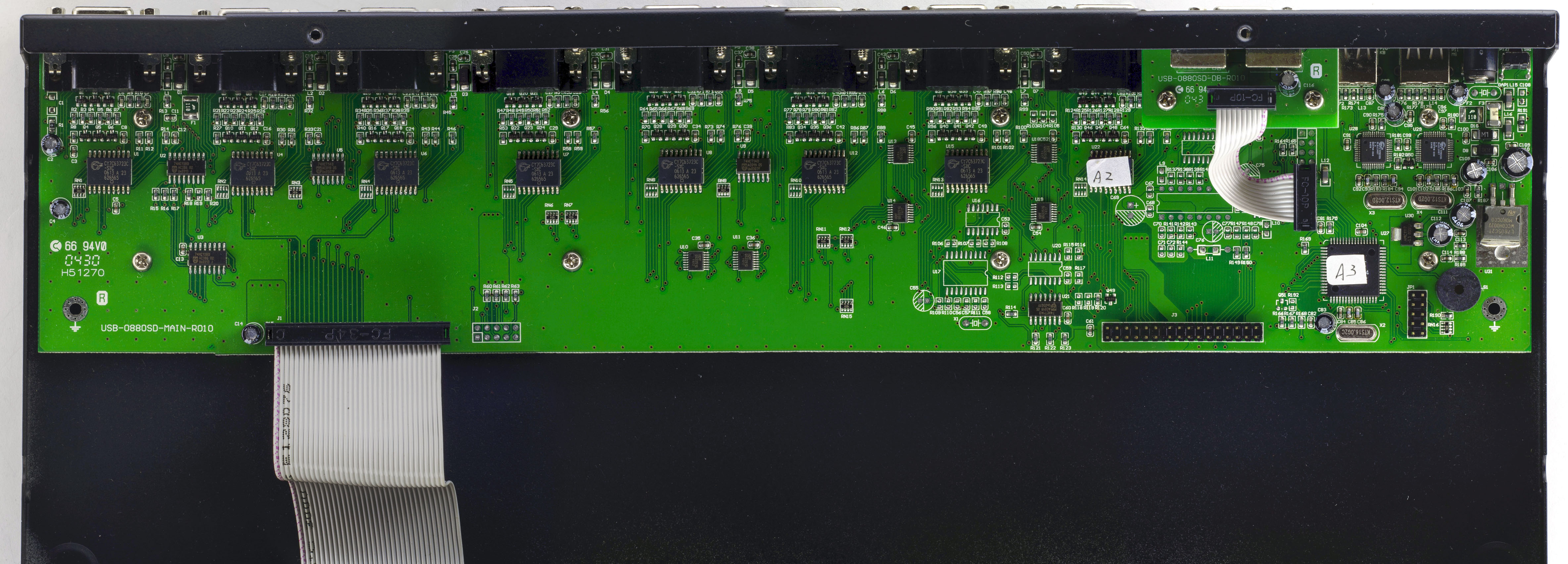
Once inside, we can see the PCB doesn’t use up all of the space available. They are using one chip 8 times (as you might expect), have a little bit of logic (2x 74HC13 and 2x 74HC14), there’s a main chip and a chip for each USB port. There is a 6x 2 pin header for the main chip, the front panel buttons/LEDs connects via a 34 pin connector and there is another 34 pin connector spare with some unpopulated components nearby, wonder what other functionality they could have added. PCB date is 30th week, 2004.
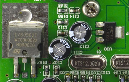
The input voltage to the KVM is 9V so we have an ST L7805 bringing it down to 5V with a decent pad for heat dissipation plus an AMS1117 LDO.
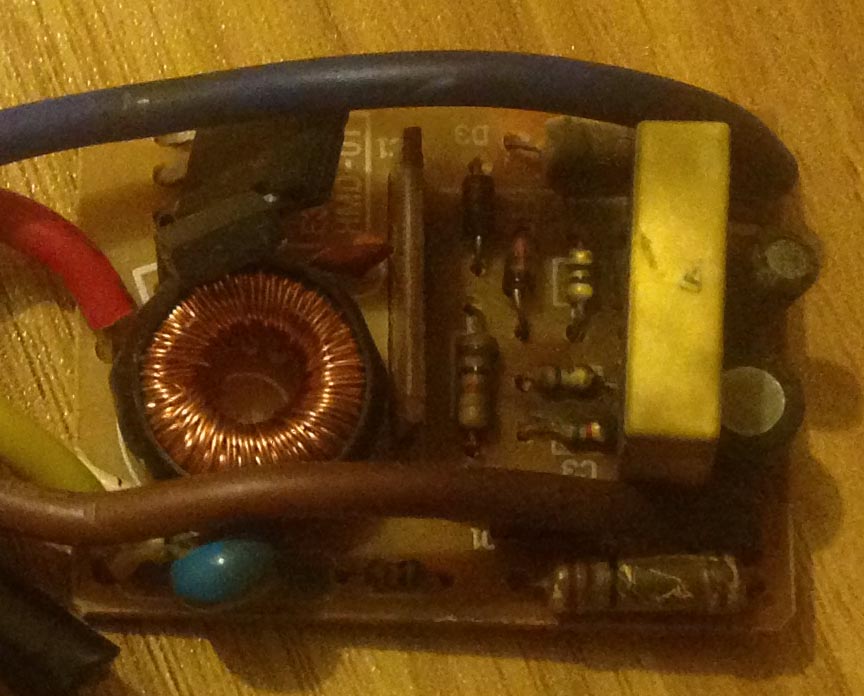
We had a working touch lamp and then all of a sudden it wouldn’t work anymore, it’s happened to a similar lamp, these lamps are probably 10 years+ old, it’s a Mirabella TL007.
After a quick inspection, the circuit board didn’t smell or look too good. We could try to find the fault and repair the board but I thought it might be more interesting to make our own touch lamp with an ATtiny and just re-use the existing lamp base.
I won’t be wiring it up to the mains, instead since I have an alarm clock already running at 5V (with an 3.3V LDO), I can just wire up directly to the 5V source. The LED will just be one of those 1/2W LEDs you can pick up off Ebay for $1-2 so we’ll just need some dropper resistors or if you wanted to, you could make or buy a constant current driver.
For the touch sensing, you can buy a chip to do that (or it could be integrated already to an MCU you choose) or do it by hand, of course I went with the by hand method as I’ll be using an ATtiny13A. Once touch is detected, we’ll just turn on a mosfet to power on the LED.
To start off, we can use the ADC on a pin to look for any voltage fluctuation but we can’t just leave the pin floating, the pull down resistor needs to be high enough that the pin won’t float, can’t be too low or it won’t detect when we touch it, for me that ended up being 4.7M ohms.
I’ve recently started to replay some Gameboy games on my Gameboy Colour, I picked up a Gameboy Advance and eventually got around to doing the AGS101 mod to it which makes it look really nice. Eventually I got to the point where I would have to keep recharging the AA batteries I was using as they weren’t lasting as long and the weight of the 2x AA 2000mAh rechargeable batteries made the GBA feel a bit heavy.
I saw a post where someone fitted a 2000mAh LiPo battery to their GBA, they had do to some modifications to the GBA battery compartment to fit it all. By using a LiPo battery instead of the AA’s, it would save us about 20 grams, while not a lot, ever gram does count and you can tell the difference plus since the LiPo has a higher voltage, it has a higher energy density, so it should give us longer play time than the AA’s. So I decided I would do the same mod and I might make a little voltage regulator and charging board to go along with it.
We can’t just directly hook up the LiPo battery to the GBA, you have to step it down to around 3V. You could go higher but I chose not to as who knows what that might affect seeing as the the GBA has a DC-DC boost converter on board stepping it up to 3.3V/5V.
A DC-DC buck converter could do the job to reduce it to 3V and so could an LDO but from my experiences, both of these options seemed to have quite a high quiescent current (usually around 1mA), we would waste power even when the GBA was powered off. One way around this would be to keep the device in shutdown but then how would you detect if the GBA was powered on?
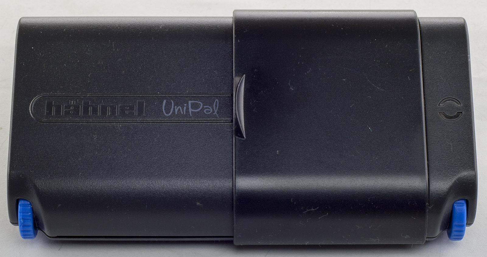
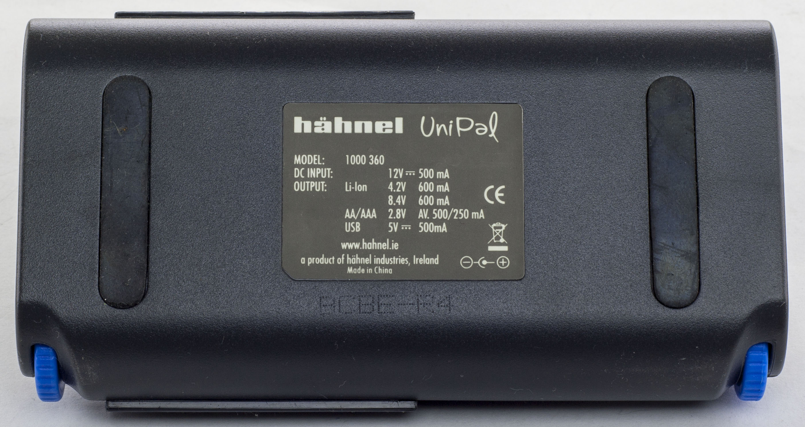
Just a quick one today, we’ll be taking a look at Hahnel UniPal Universal Battery Charger which can charge AA/AAA/Li-Ion and also outputs 5V for USB. This charge allows the user to change the Li-Ion battery contacts via the blue gears.
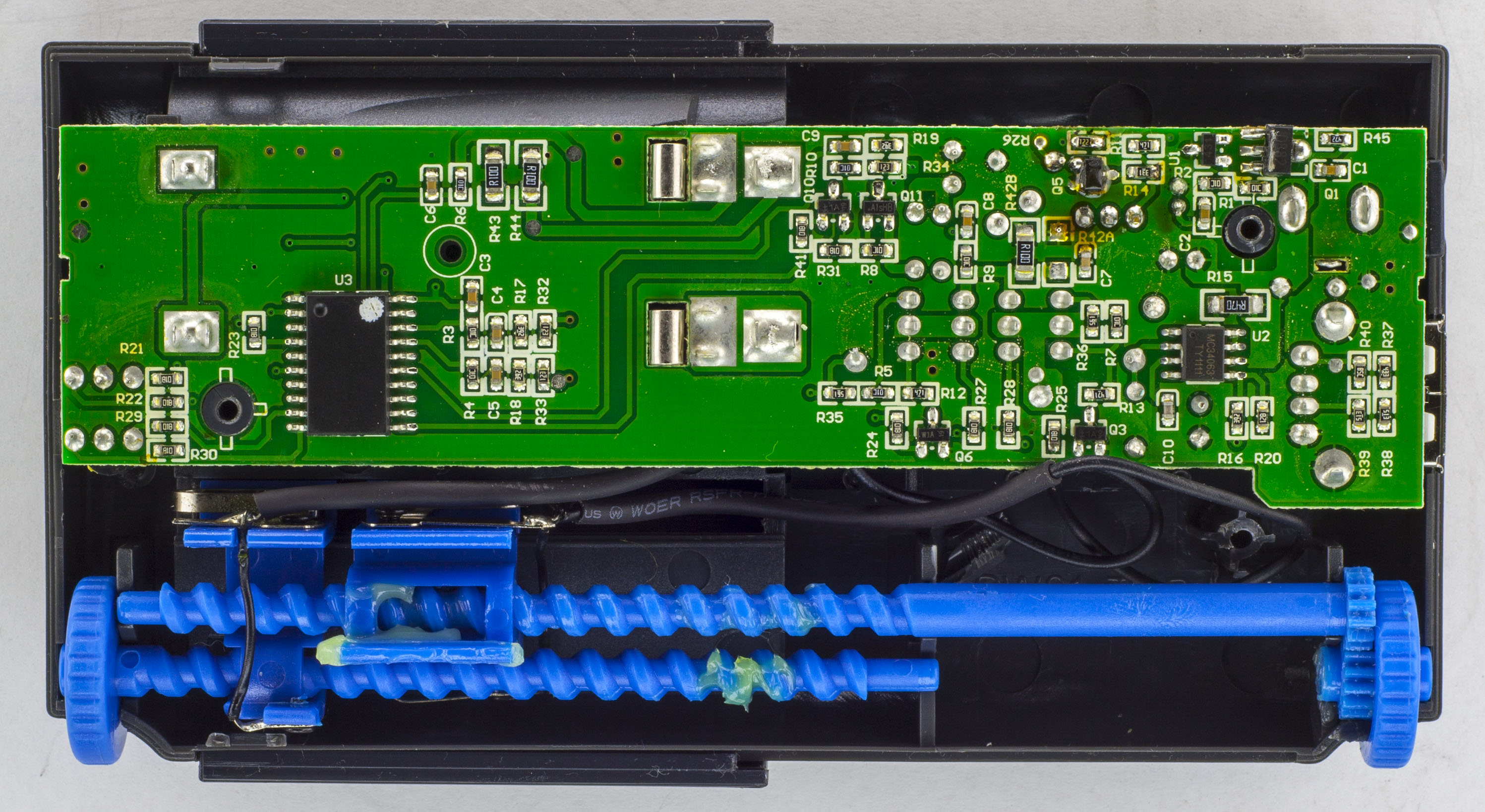
3 screws later and we’re in.
There isn’t too much going on, just a single chip solution and there are no marking on it. You can see how the blue gears and the wires going to the contacts have been heat-shrinked to protect them a bit more.
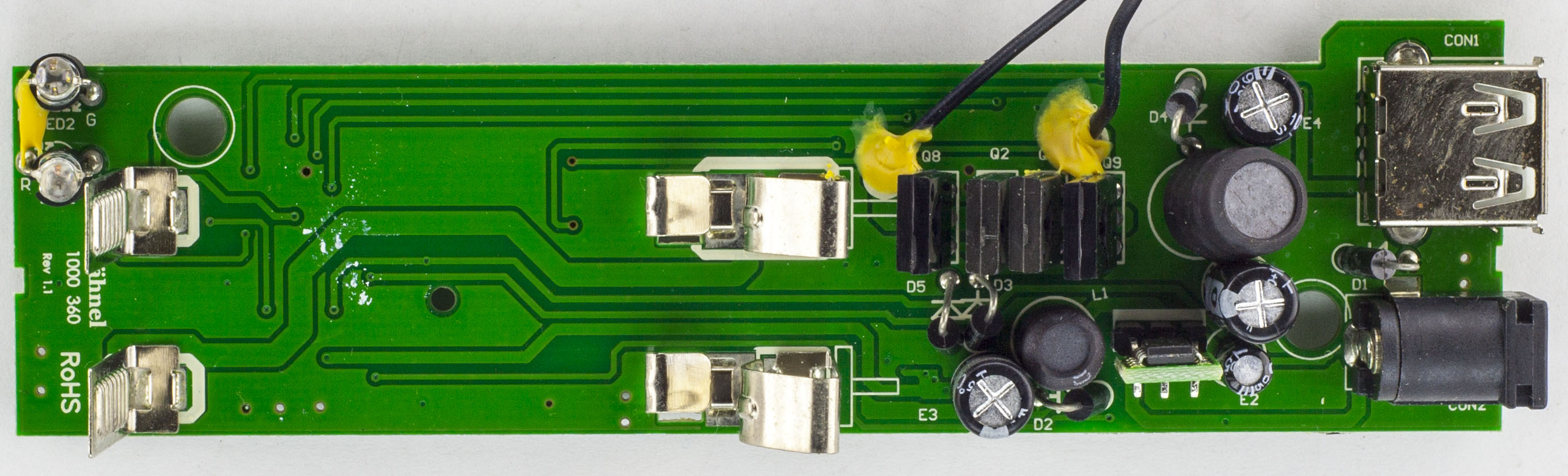
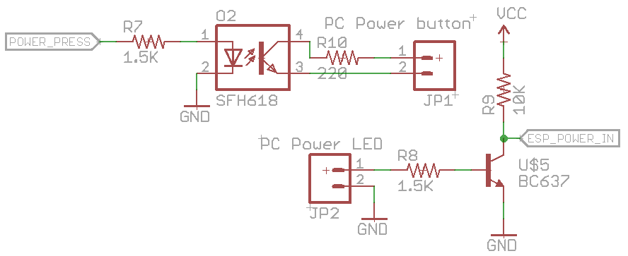
I know this sort of project has been done before but nevertheless it’s still an interesting project to try and put your own spin on it. The idea is to have an ESP8266 which can press/hold the power button and might as well have it also read the power LED state, you could also wire up the reset button if you wanted to, it’s a good concept for servers (or PCs) which don’t have a remote management and you need something basic.
(sneak peak of prototype)
One option might be using the 5V standby power which most power supplies provide when the PC is off. Some PCs might have 5V standby available in the BIOS, the keyboard and mouse might stay on, maybe you could find some pins on the mainboard but perhaps some mainboards might not have it? Let’s just avoid it all, I’m thinking I could have the ESP8266 powered off a 3.3V LiFePo4 battery in a small little case which when the PC is on, it will recharge itself via USB, this way we don’t need the PC to be on or have the ESP8266 powered via a mains adapter.
For the circuit, we can sense the power LED, it will have a voltage drop out say 2-3V with the LED but could have 5V if the LED isn’t connected for whatever reason, we’ll just use a NPN to switch 3.3V on or off to our input pin. The power switch we can use an opto-isolator to turn it on or off which can be inline with the power button. We can also integrate the USB LiFePO4 charger into this project to charge the battery.
That’s pretty much all there is to the hardware, now for the software which is where it’s all at. We want to make it as simple as possible to setup without needing any port forwarding on the client’s end, so the design is to have the ESP8266 reach out to a server to fetch a command over HTTPs. We don’t want the ESP8266 to be awake all the time otherwise the battery won’t last long so we’ll utilise the deep sleep function and say wake up once every 5-10 minutes.
I’ve built a 32KB Gameboy cartridge before to add support for certain flash chips to GBxCart RW but those were wired straight through without the need of an MBC so I thought it might be interesting to jump back into CPLDs by building an 2MB Gameboy cart.
We have a few options when building a Gameboy cart, use 5V Flash chips (which are pretty rare these days) with 5V SRAM chips or go 3.3V Flash/SRAM chips and use level shift transceiver with direction control to interface with the Gameboy’s 5V logic. Because this is my first real cart, I’m going with easier the 5V flash/SRAM chip option for the moment.
(sneak peak of the cart running a game)
The only flash chip I have on hand is the 512KB AT49F040 so I’ll use that at the start and then we’ll transition to the 2MB AM29F016B in a later part once it arrives. For the MBC, I have an Altera EPM3032 CPLD handy so we’ll go with that, it runs off 3.3V so we’ll need an LDO for it and the inputs accept 5V logic.
Initial Planning
Let’s get started, firstly we’ll review the MBC5 documentation to determine which addresses the CPLD will need to read for changing ROM banks/RAM banks, etc. The lowest address is 0x0000 – 0x1FFF for RAM enable, the highest bit of that address that’s a 1 is A12 so that’s where we will start. The highest address is 0xBFFF when accessing the RAM, so A15 is where we will end, that makes 4 bits which are needed for listening to incoming MBC requests.
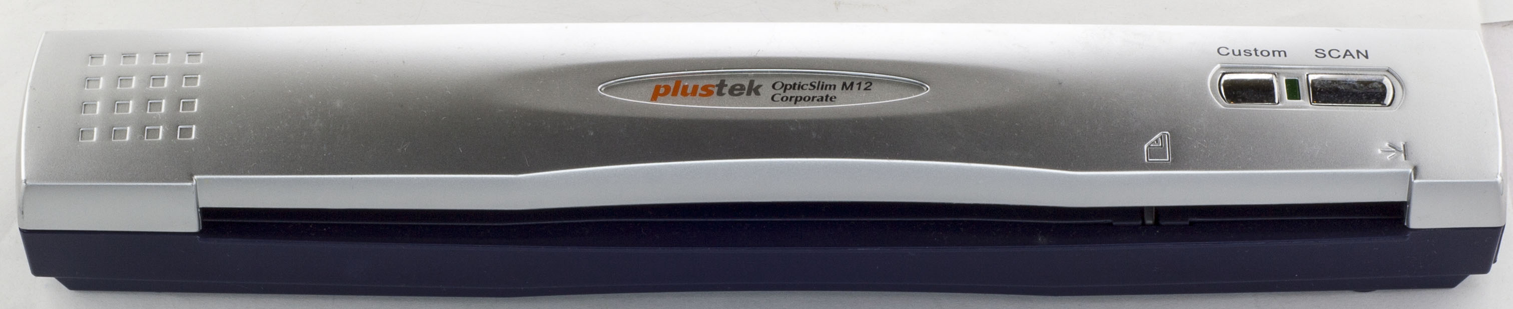
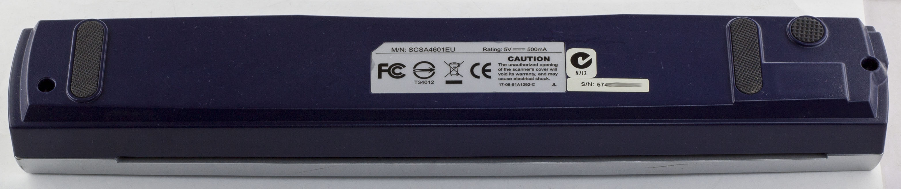
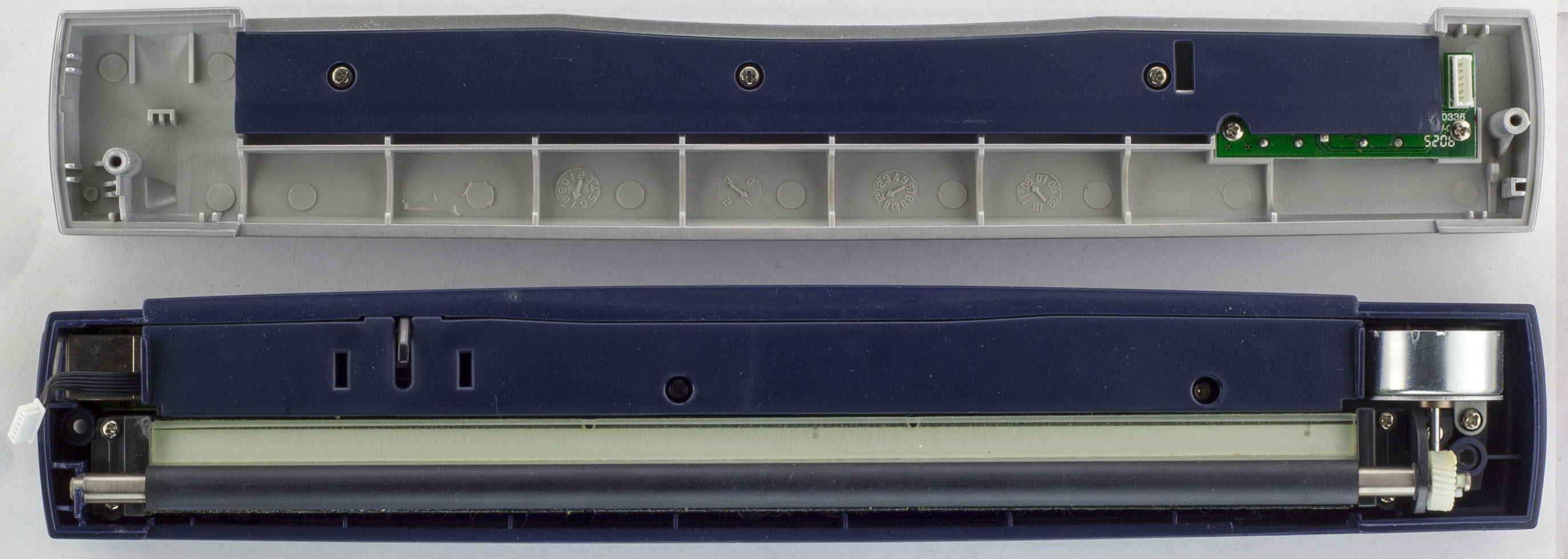
Today we’ll be taking a look at Plustek OpticSlim M12 Corporate USB Scanner which is a single sheet scanner, powered by USB.
2 screws later and we’re in.
The shell comes apart, we have the small buttons PCB on the top and the scanner and motor on the bottom. A few more screws later and we’ve got to the main PCB.
We have a relatively long PCB that has single chip solution with a motor driver. The scanning element was connected with a flat flex cable. PCB date code is 1st week of 2007 but it’s strange that they have another date code of 2002 on the board, maybe this PCB was part of an older product.
AdvanceVGA – Play your GBA on the big screen! Swap out the LCD for our board, solder some wires, connect 5V USB and VGA and you’re ready to go.
GBxCart RW allows you to backup GB/GBC/GBA ROMs, save or restore game saves and re-write supported flash carts. Mini RW option available for GB/GBC only.
Wireless Gameboy Controller – Use your Gameboy, mGB, GBC, GBA, GBA SP, GB Micro, NDS and NDS Lite as a wireless controller on Windows, Linux, Raspberry Pi, etc, and on your NES, SNES, N64, Gamecube and Wii.