Following on from Part 4, we looked at adding the sirens, SMS sender and the modifications needed to the server. In this part we’ll look at modifying the PIR sensor so we can add on the wireless client to turn it on and off.
This should be simple enough to do, just add a mosfet on the switch of the PIR and that should be it. However one thing I didn’t take account of was when you turn on the PIR, it transmits it’s signal to the alarm system like it was triggered which is a big problem.
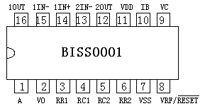
We need to go back to the BISS0001 datasheet to see what we can do. Firstly I tried to pull 2Out low before powering up the PIR but it made no effect.
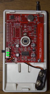
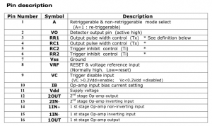
After looking at the datasheet more there is a Trigger disable input (pin 9) which is enabled if the voltage is more than the supply voltage (Vdd) * 0.2. On the board I found a 1M resistor connecting the supply voltage to pin 9.
What we should be able to do is ground pin 9 and the 1M resistor should take all the voltage drop leaving pin 9 grounded. I tested this out and it works – you ground it before turning on the PIR and then a few seconds later you disconnect it from ground; another mosfet here should do the trick.
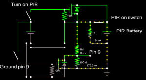
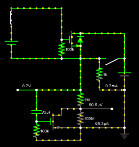
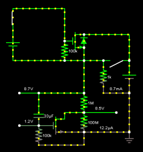
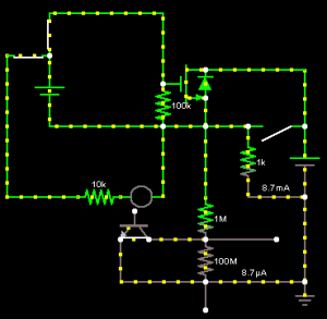
Here is how the circuit looks simulated when the PIR is on via the PIR on switch. In the middle we have our 2 mosfets, the left switches represent our MCU pins going high to turn on the mosfets and on the right we have the PIR on switch, the load as 1k and pin 9 as 1M with load 100M. (I should be using a P mosfet but didn’t have a DIP one available and it doesn’t seem to affect the circuit at all since it’s low current)
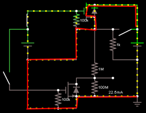
Now what happens when we turn on the first mosfet to power on the PIR is that the current takes the less resistive path which is actually to ground.
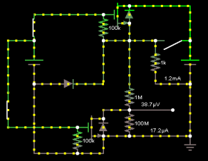
Adding a diode corrects this issue and now we can turn on the pin 9 ground mosfet and it seems to all work in the simulation.
However when actually testing this out with the MCU to turn on both mosfets it didn’t work, one mosfet would work but the other wouldn’t. When you removed the gate of the mosfet from the MCU and put it on the battery to turn it on manually then it would work – so the MCU must be allowing some current to flow back from the mosfet’s source. I tried adding a diodes from the MCU to the mosfet’s gate but I didn’t have any success. If there is a way to remove 1 mosfet from the MCU side then things would work.
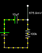
I was thinking about how would you be able to turn a mosfet off after being triggered and played around with making an RC circuit – a resistor capacitor circuit. By using an RC circuit we can slowly charge the capacitor and then trigger something to happen after the capacitor has charged or vice versa – kind of like a time delay.
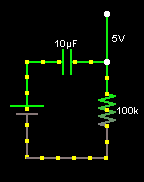
An example is using a 10uf capacitor with a 100k resistor. When connecting the 5V battery, the voltage of the capacitor is 0V and starts to charge – the input to the resistor reads 5V.
After 2 seconds, the 10uf capacitor is almost charged to 5V and the input to the resistor reads 0.7V.
We can apply an RC circuit to the mosfet that grounds pin 9. After testing I found that a 33uf capacitor with 100k resistor works best for me. When we turn on the PIR, the capacitor starts charging and because it starts charging, the voltage on the 100k resistor starts at 8.7V or more which turns on the pin 9 mosfet.
After about 5-6 seconds of charging, the capacitor is almost fully charged, the voltage on the 100k resistor drops to below the mosfet’s Vgs (on) voltage which turns the mosfet off. Now the PIR turns on, pulls the trigger disable low for 5-6 seconds and then lets it go back high after which results in the PIR not sending it’s start up trigger to the alarm system.
But what if the PIR was turned on and then 10 seconds later it was turned off? The capacitor would still hold charge for at least 10-30 seconds or so; if we turned the PIR back on it would send the start up trigger. My initial idea to solving this was to hook up a mosfet with a resistor that would drain the capacitor after the PIR was off but things were getting too complex.
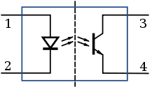
After looking for a solution, I remembered that most power supplies use an optocoupler to give feedback to the low voltage circuit from the high voltage circuit.
An optocoupler works by switching on an LED inside the device and having a light sensor on the other side to detect the LED which gives electrical isolation, you could almost think of it as a very small relay.
We can put the optocoupler to pull pin 9 to ground and it works – a much simpler circuit than the RC / mosfet circuit.
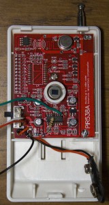
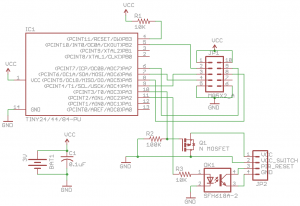
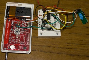
Here is the updated schematic and how it looks. We are now set and have all the pieces for the alarm system ready.
In this part we found that using mosfets with a device that we don’t know how it’s laid out can sometimes cause problems. We learnt about how to use an RC circuit and finally how an optocoupler can help us when we don’t want make an electrical connection between 2 circuits. For the next part we’ll make our PCBs and do some testing.
Part 1
Part 2: Two way communication for PIR sensors
Part 3: Secure communication
Part 4: Adding on sirens and SMS sending
Part 5: Modifying the PIR sensor
Part 6: PIR PCB
Part 6.5: PCBs arrived
Part 7: See which sensors check-in
Part 8: Building our own alarm system
Part 9: Remote control and attempted improvements
Part 10: Prototype PCBs


Hi, I am working with that BISS0001 chip too, but cannnot find the datasheet in a readable language (only Chinese).
Please can you help me on a copy in English?
Kind Regards,
T.A.
Hi T.A,
The only one I was ale to find is the summarised english version here: http://learn.adafruit.com/system/assets/assets/000/010/133/original/BISS0001.pdf
Hi,
I am trying reverse engineer a pir infrared led light which i bought locally (Manila, Phillipines).
What i need to achieve is to replace the the led light with a much higher voltage led (around 12 volts) as the light is not that bright enoung to light a small room.
I can email you the inside picture of it for better appreciation. I have posted alink just to give you an idea of it as well. Thanks!
http://www.cdrking.com/?mod=products&type=view&sid=9729&main=135
Hi Sam,
One quick way would be to grab the LED’s positive wire connect it to the gate of an N mosfet (also add a 10K to 100K resistor from the gate to GND), have your 12V power supply connecting to your new LED (with resistor or current limiting) going to the mosfet drain and mosfet source to GND.
Hi,
I have a project that i was trying to build..the concept was i will use a motion sensor to trigger a relay, this relay need 1 time pulse to trigger the relay,is there anyway to use this motion detector?we will use these project to a drive thru.
Thank you,.
Hi Aldrin,
Yes you can use the PIR sensor, if movement is detected, it sets the output pin high for a certain amount of time which in this PIR was adjustable by a pot. You can hook up a transistor to the relay to turn it on for a few seconds or you can use a 555 or microcontroller to increase the time your relay will be on for.