In one of my previous posts, I integrated the LM2596 module into my SPPS project, I’ve been trying out a RAID5 array with 4 hard drives attached to my Raspberry Pi and now it’s time to think about how to power it all. Each hard drive takes about 0.7A on the 5V and 12V rail plus about 1-2A for the Pi so 5V @ 5A and 12V @ 3A but the peak current will be a bit higher when all the hard drives start up; I could use a couple of LM2596 modules but I’d rather build my own.
I’ll need something other than the LM2596 that can deliver a bit more power which is where the MC34063 comes along when in the right configuration.
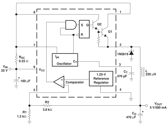
The MC34063 is a buck/boost/inverting switching power supply, you add in a few parts and then it’s good to go. The way a switching power supply works is by using a oscillator at a fixed frequency and a voltage reference with comparator to turn on the mosfet in line with the oscillator when needed, this ensures that the mosfet isn’t fully on all the time.
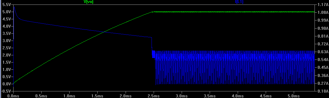
The current from the mosfet passes through the inductor and when the mosfet turns off, the current passes back through the diode and eventually the inductor will charged up to the voltage we require; and once reached, the mosfet only has to provide short bursts of current to keep the voltage stable – you can see this in action in the above simulation (green is voltage and blue is the current passing through the inductor)
There are a few different calculators around, some online and some that use Excel. Here’s a list of the ones I’ve used:
Some of them give slightly different results to each other, so in order to know what could potentially happen is to simulate them, I say potentially because you never know what is really going to happen once you build it all up.
I have a 19V supply and using one of the calculators the resistor feedback needs to be 3K / 1K for 5V output.
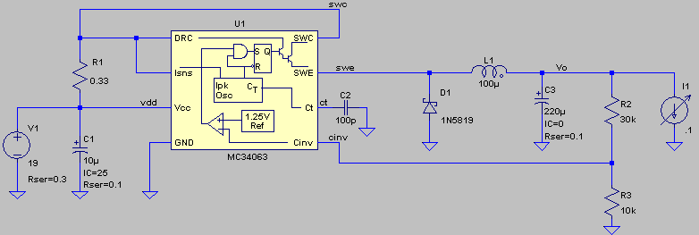
Using LTspice and the MC34063 model we can see what changing the parts such as the timing capacitor, inductor and Rsc (R1) does to the circuit. It takes a little bit to get used to the way LTspice works but once you do it’s very helpful, if you’re new to it – open the asc file, go to Simulate > Run and then on the circuit you have the oscilloscope probe to probe the circuit, you can check current by clicking on the resistors, capacitors, etc. (The one thing that doesn’t seem to work correctly is the Isns wire when compared to the real MC34063 when you have a voltage divider on it)
Download my configuration here: MC34063_v1
The voltage spike shown above is what happens when you select an 50u inductor which is too small with a 0.1A load with 100KHz timing.
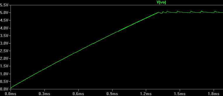
Changing the timing capacitor allows the voltage to rise quicker but can potentially give you more fluctuation when the voltage reaches 5V.
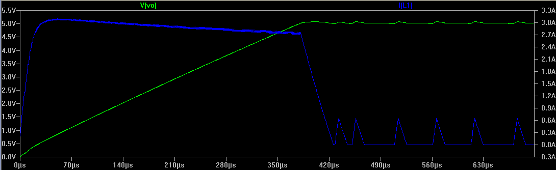
Changing the Rsc lower to 0.1 ohms allows our peak current to increase and rise time decreases. If you do lower the Rsc, you need to make sure the diode can handle the current as well as the inductor too.
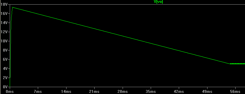
With the inductor at 100u and no load (apart from the resistor divider), it seems to work fine even if the calculator says that the minimum inductance for a 0.1A load is 389u when at running at 100KHz. The lower your load, the more inductance you require and the higher the oscillator frequency, the inductance can be lowered.
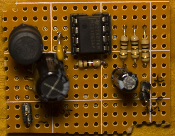
I built it all up by harvesting the inductor and schottky diode (on the underside of the board) from another board, it seems to power up the 5V rail of a hard drive without issues, it’s drawing about 0.3A without any activity on the drive. The problem with the MC34063 is that by default we can only have a peak current of 1.5A which means your load needs to be lower than 0.7A.
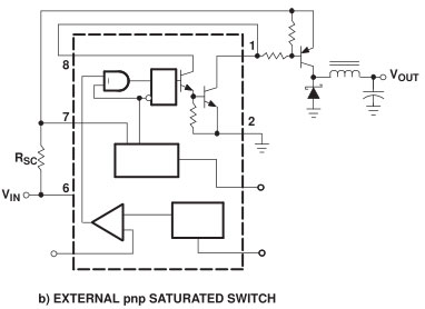
The way we can overcome this issue is by adding in a PNP transistor (page 8 of the Ti datasheet), so that the internal transistors will be driving our external transistor. There is a slightly similar configuration from the NCP3063 but I prefer the Ti one. We’ll look at this configuration with more testing next time.
Part 1: Testing the base circuit configuration
Part 2: Adding an external transistor
Part 3: Revisiting and testing with a constant current load
Part 4: Trying another DC-DC – the Richtek RT8293A, testing PCB/breadboard and load/transient test against an Ebay $1 DC-DC


hey, you said that if the peak output current it 1.5A your load can’t pull more than 0.7A, why is that ?
I just took a safe approach and doubled my load current.
In reality, from the MC34063 spreadsheet, you could go to 0.9A load and even higher load current if you increase your inductor significantly. By changing the IL / IL(avg) in the spreadsheet to a lower percentage, you’ll see the inductor size increase and peak current decrease. If the simulation which I’m doing is correct, the peak current only occurs initially for the first few milliseconds when the inductor is charging after power is applied.
Maximum collector current is 1.5A. The output current you can get is half 0.75A in a buck configuration. and even lower in boost or inverting. See the equations in datasheet
I have used Step up circuit. i have battery (1.5voltX6) 9volt/2500mampH. and i want constant 5volt/500amp. but circuit is not working with 6.5 or more than 6.5 input volt. for more than 6.5 volt it gives 6.05 (input voltage-0.45). if i supply voltage lessthan 6.5 volt then it gives constant 5 volt.
what to do? shall i try step-down circuit. what happen if my battery voltage is lessthan 5volt and i want 5volt at outputside?
Hi Alpesh,
Yes you need to use the step-down circuit, to generate 5V you need 3K/1K resistor divider and a minimum of 7.5V according to the spreadsheet. If it drops to 7.5V or less, then the 5V will be reduced too, so I’m not sure what the best solution would be to cover all of the range. If you really wanted to, you could do a step-up to 12V and then step down to 5V, but that just means more loss of efficiency (and there has to be a better way to do that).
which value of inductor should i use for 12v DC -( 13-24 DC ) & output current maximum average 1-2 A .. in many online calculator give different values for different voltage & current . DO i need change the inductor in every times ??? OR which minimum or maximum value is standard for input 12v – to variable 12-24V output and maximum 1-2A current .
I think any 15uH inductor rated at 8 amps or more should be good, it’s always best to build and check your performance.
[…] it also seems too high when looking at the application examples in the datasheet. There is a good article about a PSU based on MC34063, the author also got extremely high (389uH) inductance as a result of […]
Hi am using MC34063 for Inverting output
I have three quires
1. my i/p 12v, o/p -12v, 1.5A for this i need inductor value as well as design.
2. my i/p 5v, o/p -5v, 1.5A for this i need inductor value as well as design.
3. my i/p 12v, o/p -5v, 1.5A for this i need inductor value as well as design.
Awaiting for your positive feedback.
Thanks in advance
Dear Praveen, Sir,
For ur quire 1, u can use 50uH and u can use schema image at top of page.
For ur quire 2, more difficult at this low voltage, so u must use 5000uH, and same schema, except u must reverse polarity of diode 1N5819 and also polarity of input capacitor.
For ur quire 3, most difficult because different absolute voltages. U can still use 50uH but for entire ckt u must reverse Vin and Gnd.
We hopes ur Application is successful, and please reply here with your findings.
[…] Building a SMPS based on the MC34063 – Another good tutorial. […]
Alex,
you calculator link is dead.
I have a MC34063 calculator on my website
try
http://gmsystems.com/switching-reg-calculator-for-mc-34063-or-mc33063.html
nice blog very handy
I add alike to your web site.
thanks
Tom