From our previous post, the cases/mounts were built, a few more smaller changes were made and we added in the SMS capability. I thought that was the last change I would do to the alarm system for a long time but it turns out that the range of the remotes using the nRF24L01+ wasn’t very good, when outside the house you had to be within a few metres. This time we’ll be looking at adding 433MHz wireless to our system for the remotes to improve our range.
https://www.youtube.com/watch?v=mlmMsxs-U5Y
(sneak peak)
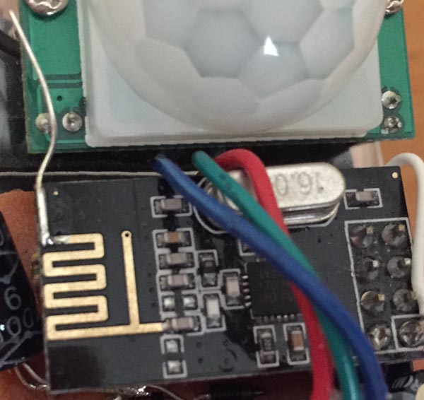
When I found the remotes range wasn’t great, I tried switching to 250Kbps operation of the nRF however I found that firstly there was an issue with the PCB antenna, sometimes it would work fine but other times I had to touch the antenna and then it works.
I added in a extra bit of wire to the antenna and that sorted it out though the range didn’t really improve much and by that time I had already switched the door/PIR sensors to 250Kbps too so I was stuck with it. So I needed a solution – could I possibly re-wire the old alarm system remotes to transmit the data I want?
Previously I made a small solar power garden light with an RGB LED controlled by an ATtiny13 and I have been thinking about how I could create a different project from it. The ability to control these RGB LEDs via wireless on demand seemed like an interesting idea – potentially you could program a sequence and have them execute it to give you a small light show if you had enough of them.
(sneak peak)
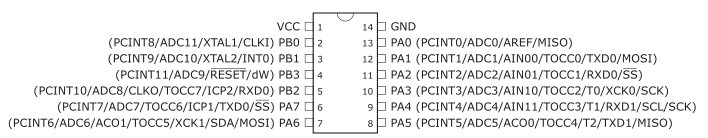
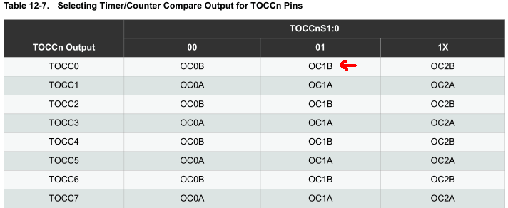
After browsing for an AVR, I found the ATtiny841 that has 3 timers which is exactly what I need to control each LED properly with PWM (another solution would be to use a WS2812 LED).
Each ATtiny841 was $1.3 so you can’t really go wrong, I didn’t know these MCUs were available so it’s a good idea to regularly browse supplier’s websites for new products. For the server side, I’m thinking an ATmega with 16×2 LCD and keypad to enter the sequence.
Client side
The ATtiny841 gives us the ability of selectable output pins for the timers which you’ll need to configure to have any output from the timer at all plus you also need to enable the timer output enable of the pin too.
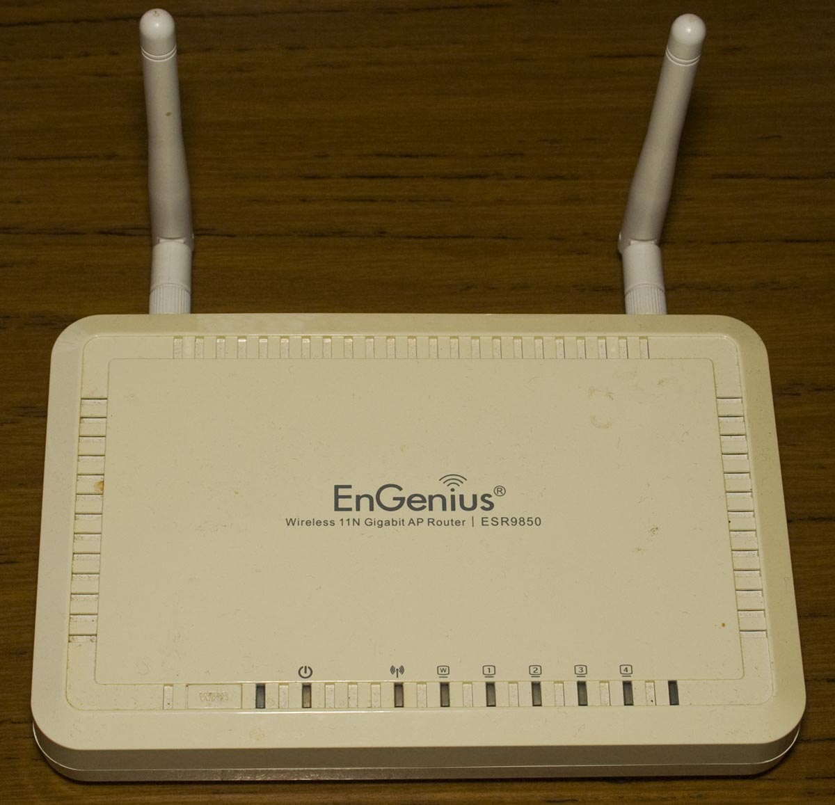
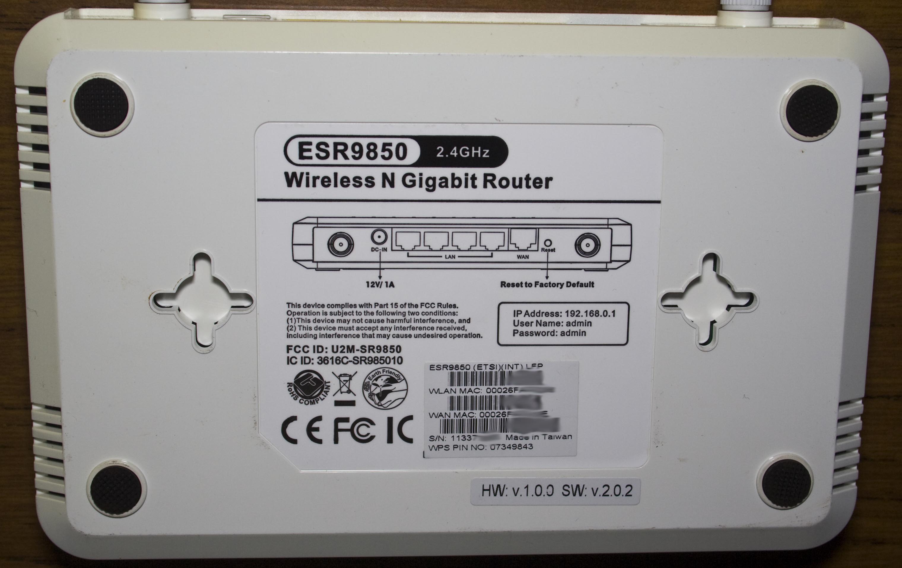
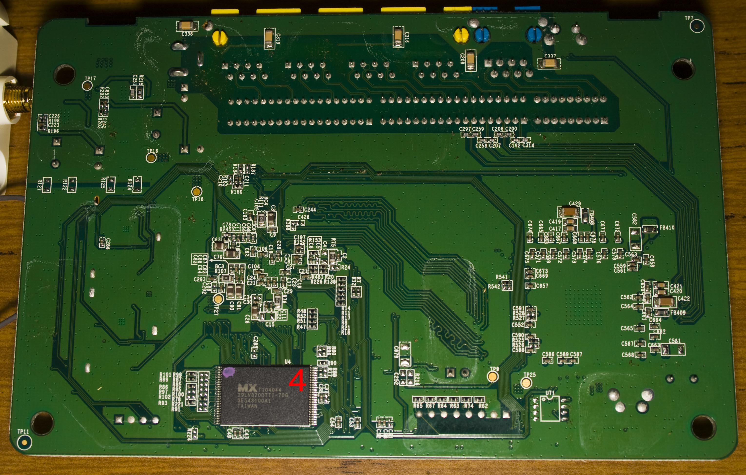
Today we’ll be taking a look at the EnGenius ESR9850 Wireless N Gigabit Router, a wireless router with 4 gigabit ports, haven’t heard of this brand before.
4 screws later and we’re in.
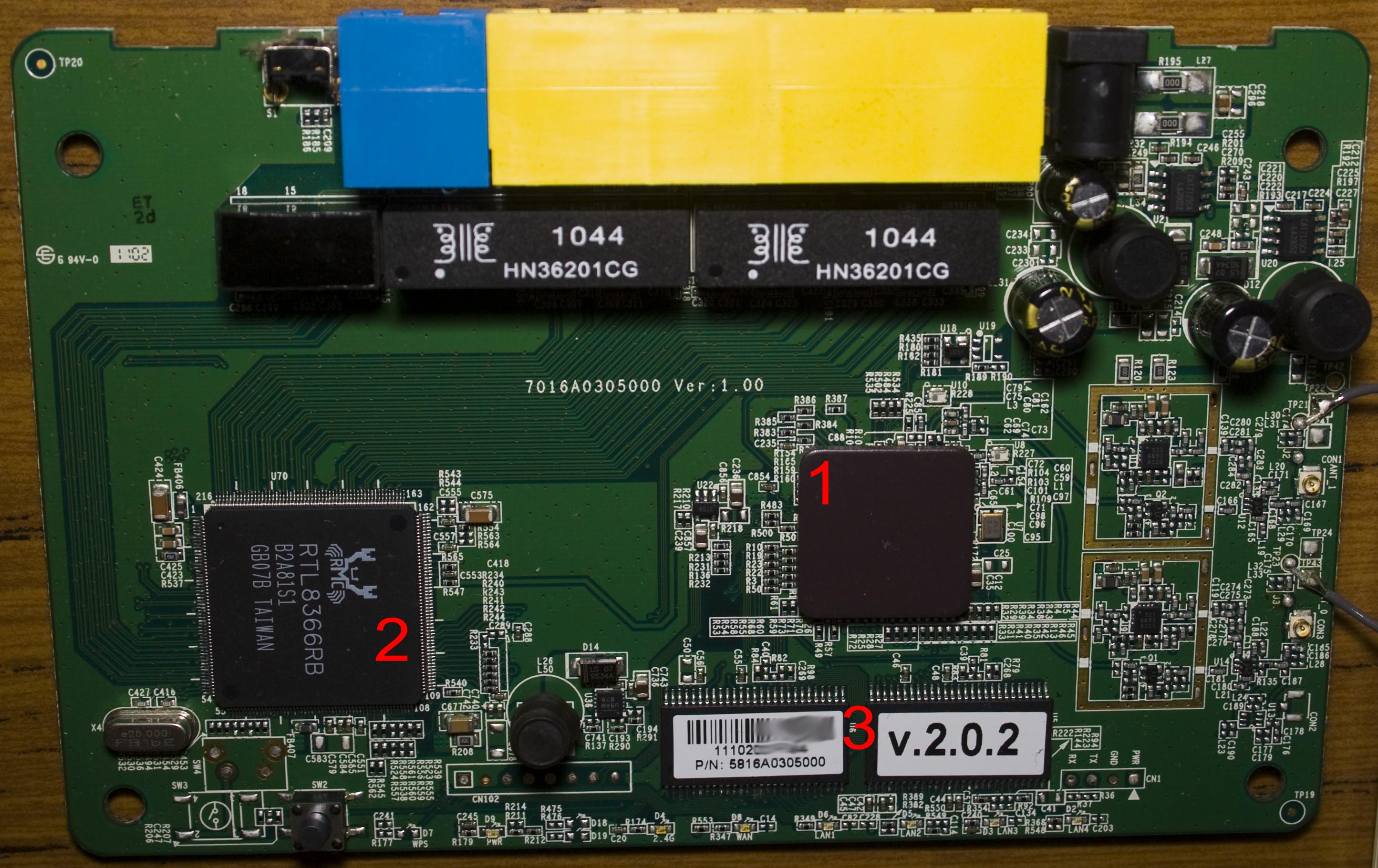
PCB layout looks quite good, we’ve got a ceramic heatsink on the main processor, 2 RF outputs without the metal cans with the antenna cable soldered on, 2x CAT7125CA SMPS up the top right plus a smaller U8AM878 one near the bottom center and a TX/RX unpopulated connector and an 8 pin unpopulated connector – likely JTAG. PCB date code is 2nd week of 2011.
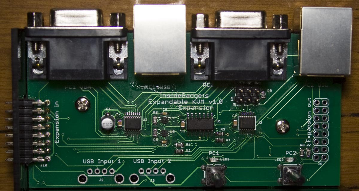
From our last part we moved over to the ATtiny24, our PCB arrived, tested good and made a quick case for it. This time we’ll check out the expansion board, a new case with changes needed to make the case work and the KVM board is now available for purchase.
The expansion board has arrived, it’s basically the same as the main board except it’s got a input expansion port instead of the VGA port. One thing I forgot to take out was the USB ports for the expansion board, so potentially if you didn’t want to use the main board’s USB connectors you could use them (I’ll take them out of the next version).
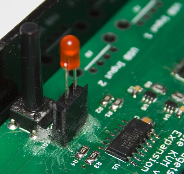
I bought some 20mm buttons and was able to solder in a 2 pin female header on the LED SMD pads so I could attach a 3mm LED to it and added some glue to hold it all in place.
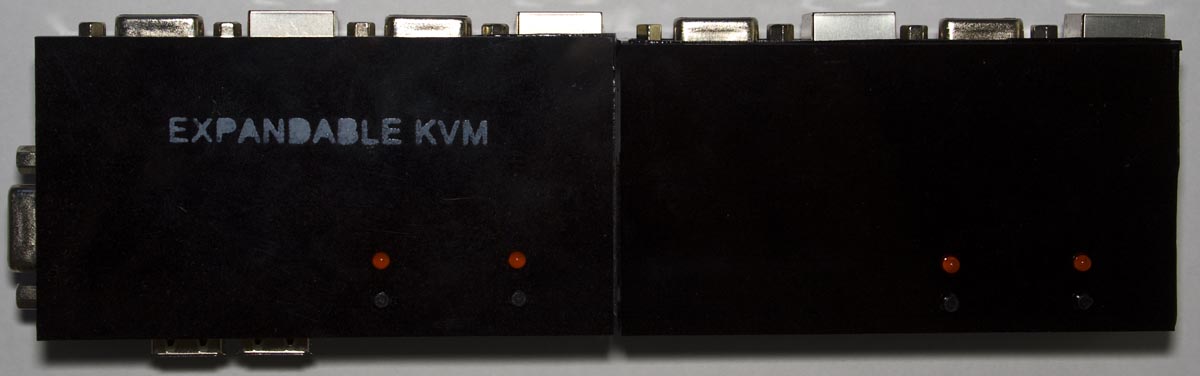
After changing the case colour to black it looks nicer and after connecting the expansion board with case too, it fits pretty well and it works. I need to put some labeling on it, the only viable method I’ve found so far was to make my own stencil from acrylic and then spray paint the name on it, you have to do a light spray otherwise it’ll seek through the stencil.
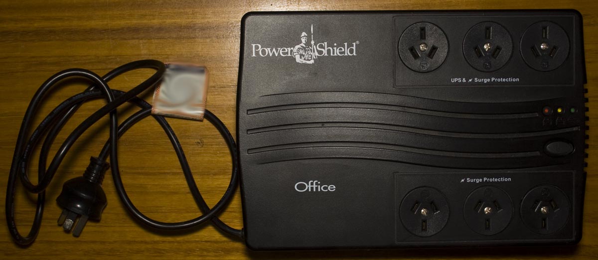
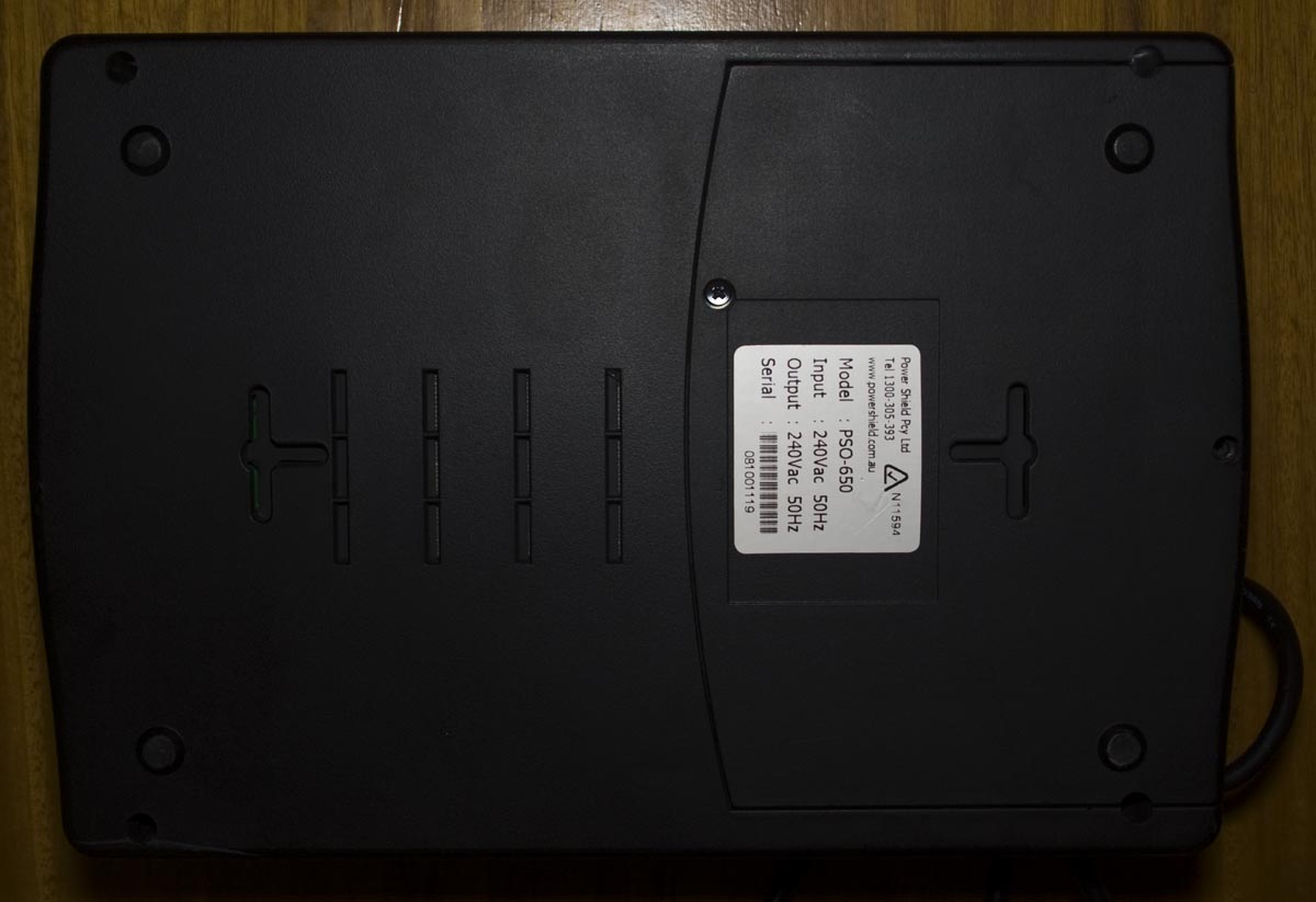
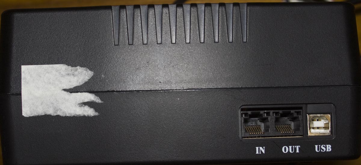
Today we’ll be taking a look at the Power Shield PSO-650 650VA Powerboard UPS, a 3+3 output UPS with surge/battery protection, phone line protection and USB for monitoring it on your PC. This particular unit failed because the 12V battery dropped to around 2 volts.
By looking at the power cord is going to tell us that this UPS is going to be built down to a price because the cord comes straight out of the UPS itself.
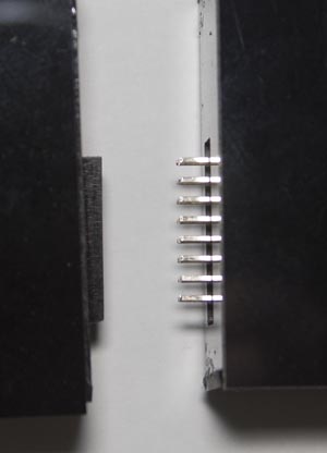
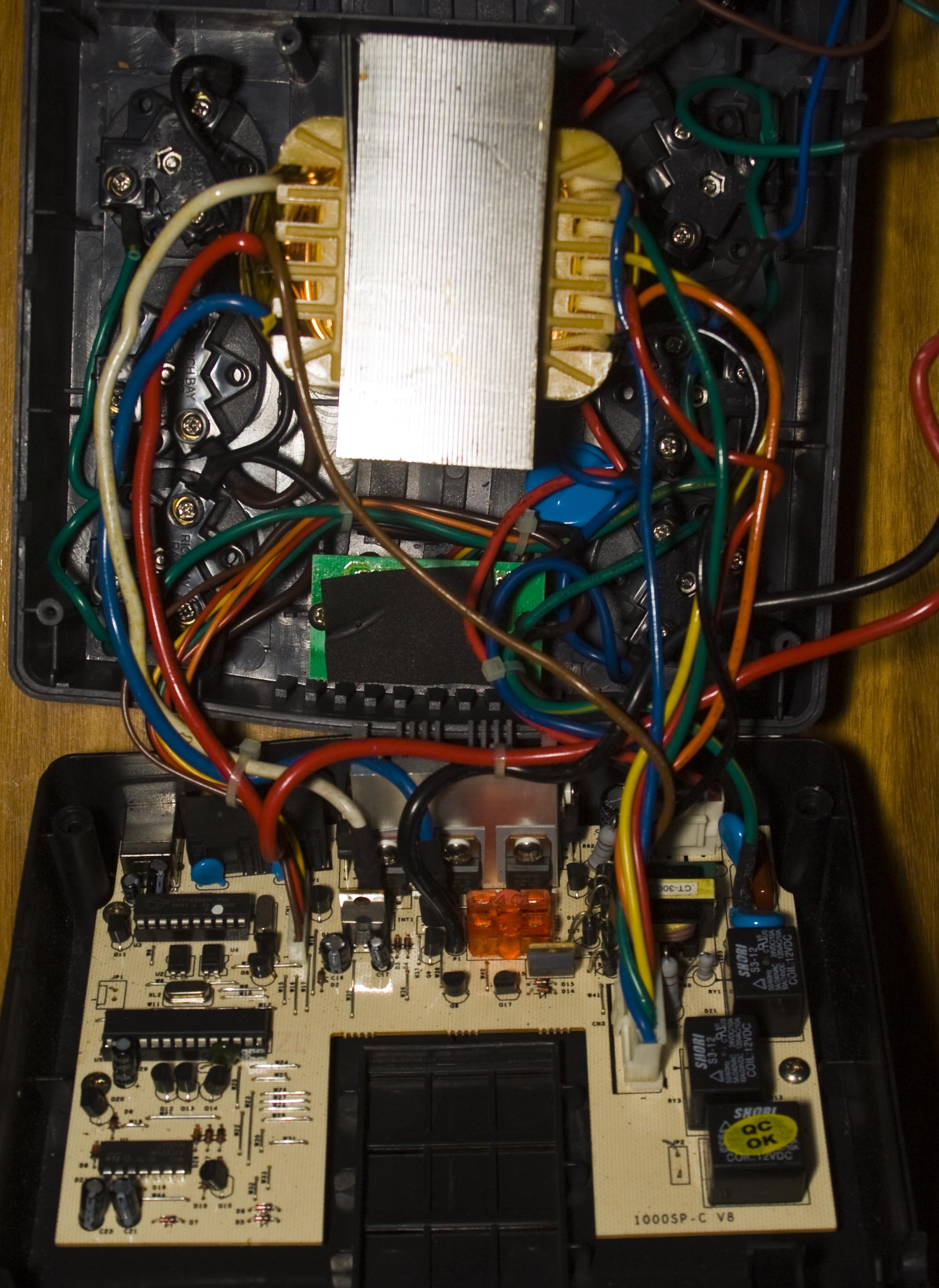
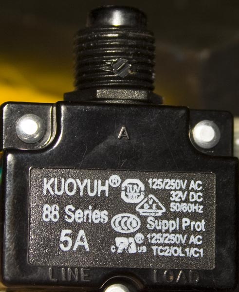
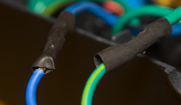
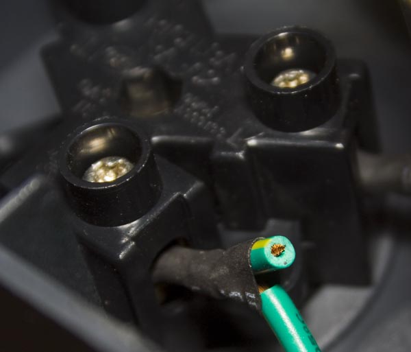
We’ve got our main PCB on the bottom and a huge transformer on the top which isn’t glued or bolted down, it just sits there due to the pressure the case puts on either end when closed. We have a 250V 5A circuit breaker on one side of the case. The surge protected outputs have some big MOVs on them. There are a few things which could be a little better, the heat shrink may have been too big that it’s pretty easy to move around and they left in an extra wire like it was meant to go somewhere else (not that it matter too much as the terminals screws are exposed anyway). The transformer is a 1065SP-2-V8/ E186x40.
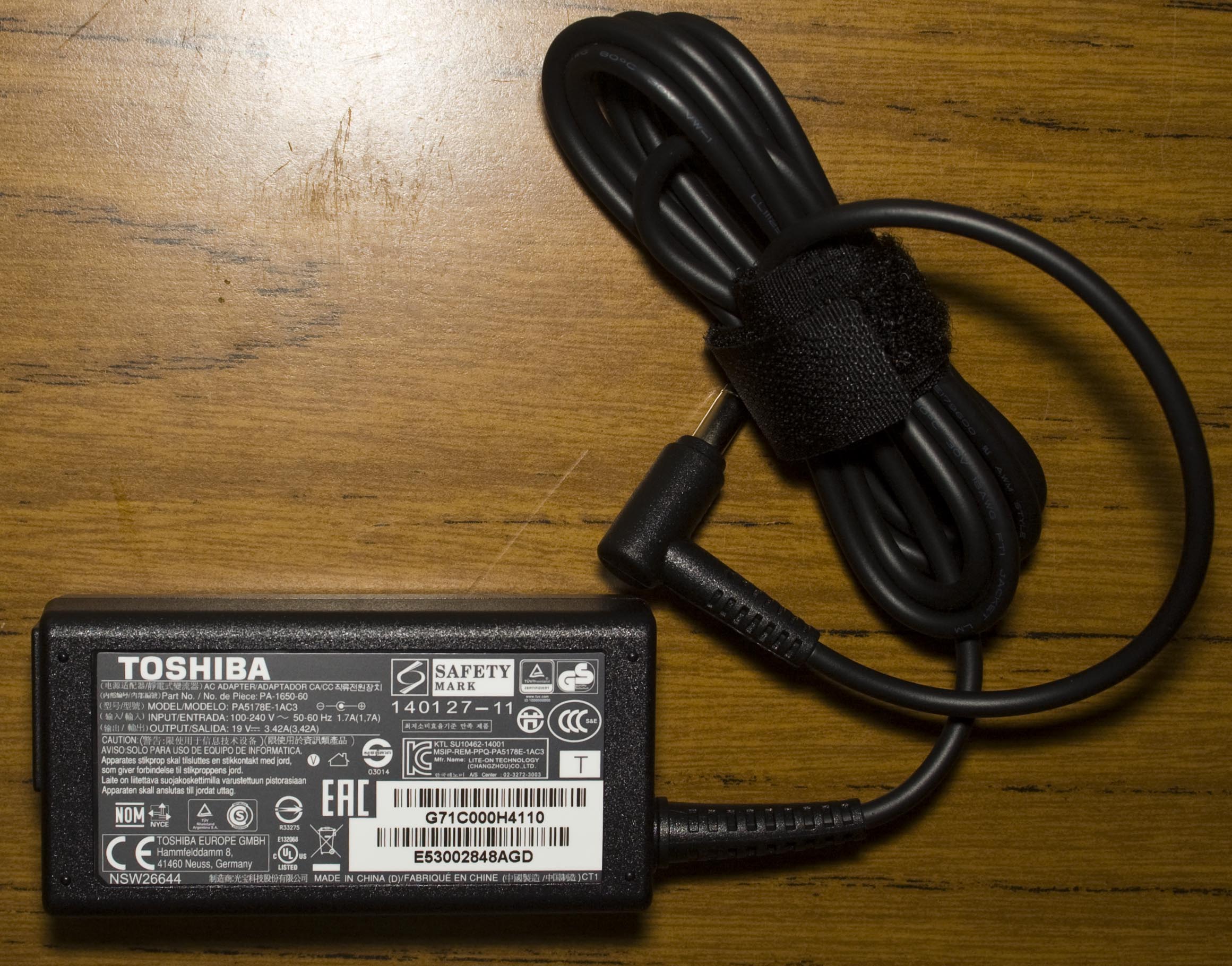
We recently purchased a Toshiba Satellite Pro L50 for a client, took it out of the box and started setting it up. About 2 hours later, I hear a bang and the circuit breaker trips. After smelling the power adapter; it smelt bad so it was likely blown, it was sitting about 1 metre away from me. Luckily the laptop survived and to Toshiba’s credit they sent a power adapter which arrived the next day (I left it running for 24 hours without issues).
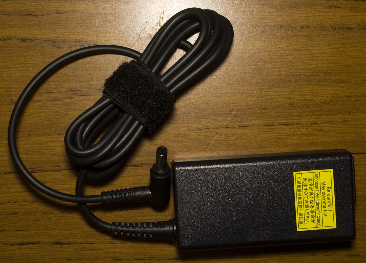
The power adapter is a 19V 3.42 (model PA5178E-1AC3, part PA-1650-60).
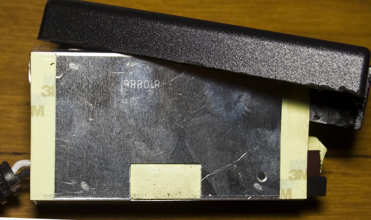
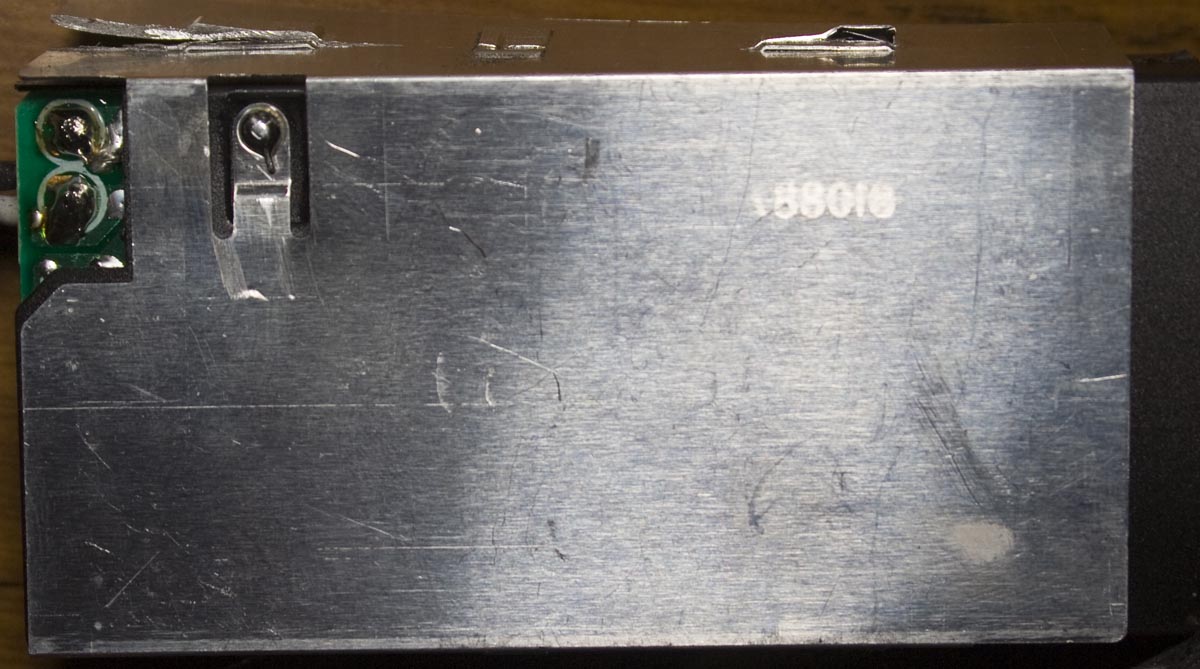
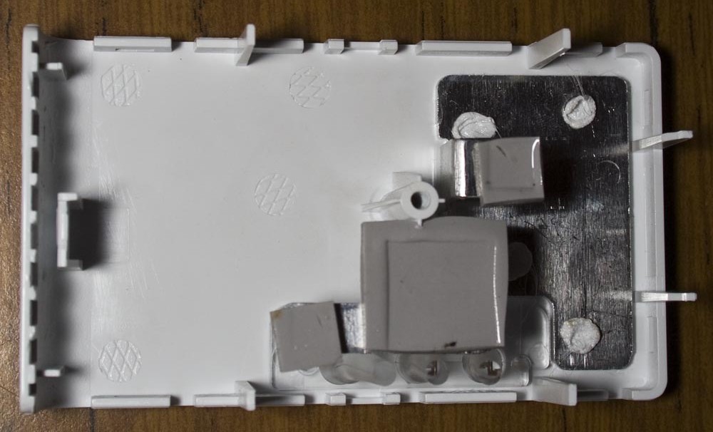
After taking a dremel to the plastic casing, we’re in. The metal shielding is connected to earth via a 1K resistor. So far no signs of damage.
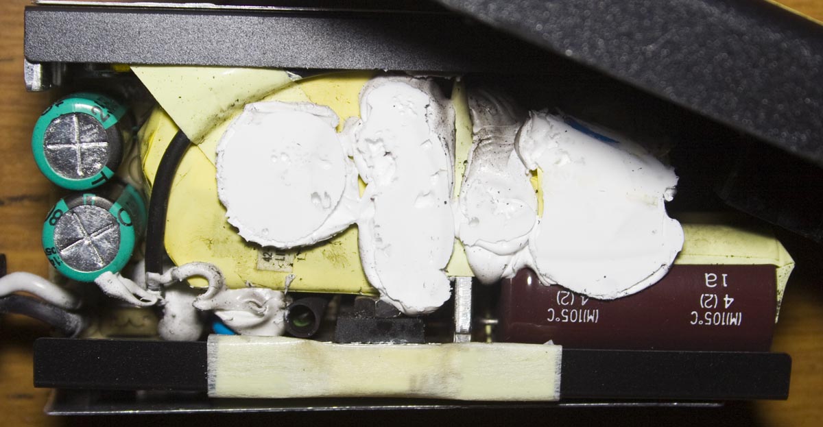
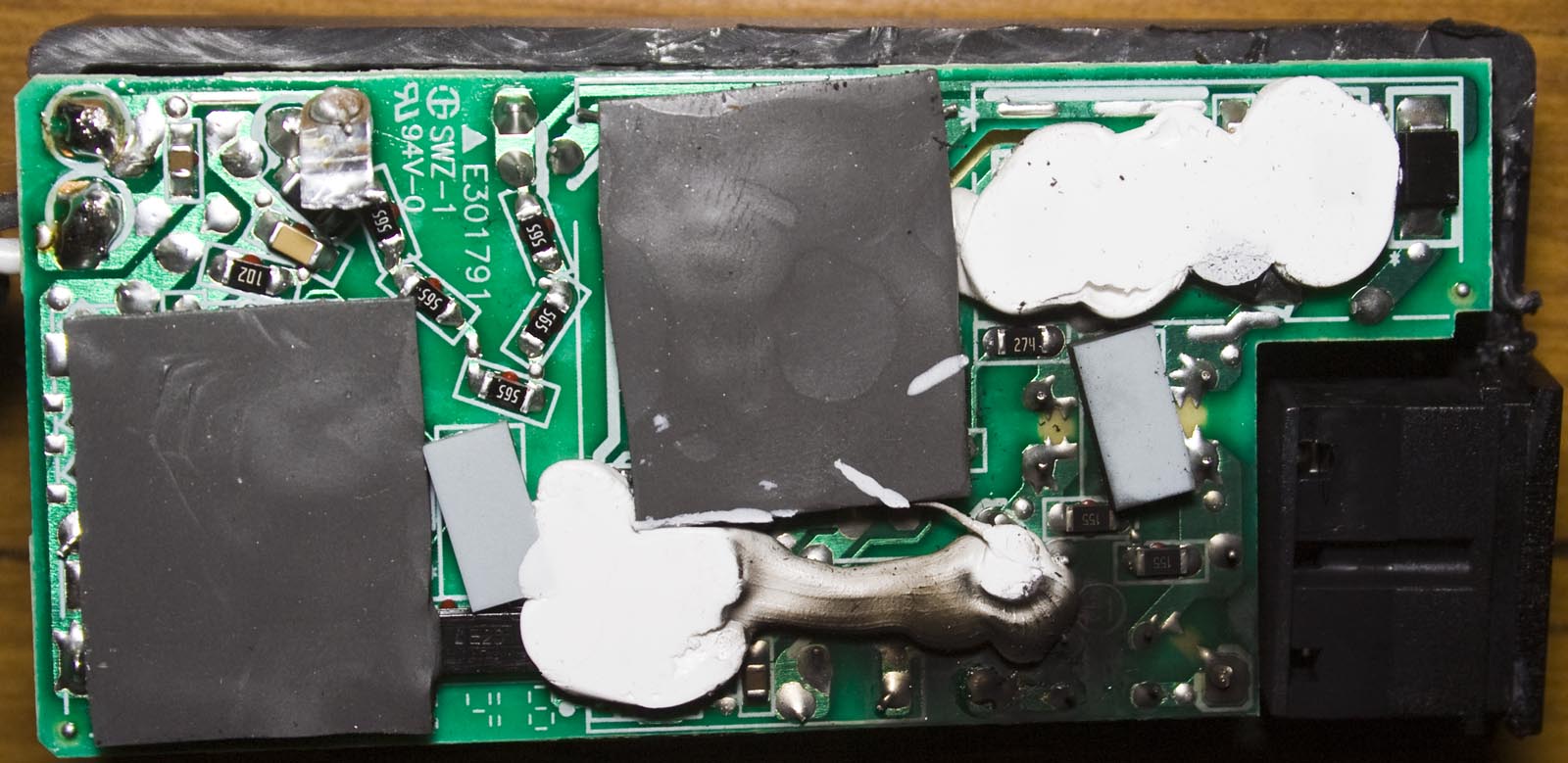
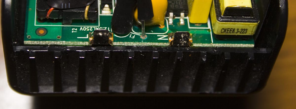
Now we see lots of charring on the bottom of the board and most of it is pointing to around the front where the mains is connected near the fuse. Just above the black connector we have the diode rectifier, notice the resistor chain to the left and the PCB’s silkscreen has good markings where the pads, rubber or glue should go.
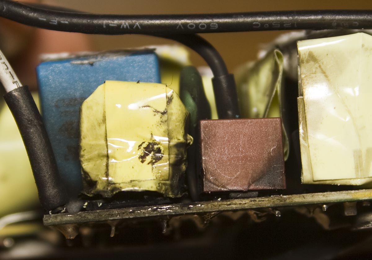
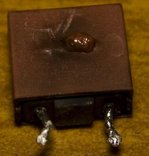
After desoldering the fuse, we can see that it’s blown pretty badly, it’s a 250V 3.15A. There must be some reason it’s blown or not?
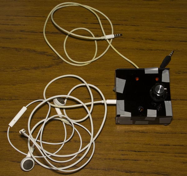
At work, we use Snom phones and we take quite a number of calls every day, when you use the handset and need to type it’s a bit difficult. There are some headset/headphones options available, the Snom uses 4P4C / RJ9/RJ10 connectors but I’ve always got my iPhone headphones on, so I’d like be able to use them on the Snom phone.
(sneak peak)
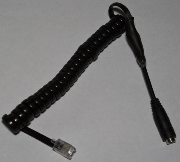
The first step was to build a Snom 4P4C to TRRS cable, I used a 220 ohm resistor for protection to find the left/right speakers and then used a 1.5K resistor for the microphone.
It turns out that the microphone was a little hard to hear so after removing the 1.5K resistor it sounded better but it wasn’t loud enough unless you place the mic close to your mouth.
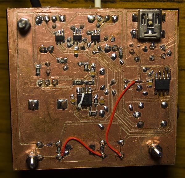
After speaking with a colleague, the idea came about of being able to switch between an iPhone and the work desk phone easily, it shouldn’t be a problem since we can an analog switch to do this. I had the Ti SN74LVC1G3157 SPDT switch on hand and it should do the trick, just hook up 3 of these for the mic and speakers.
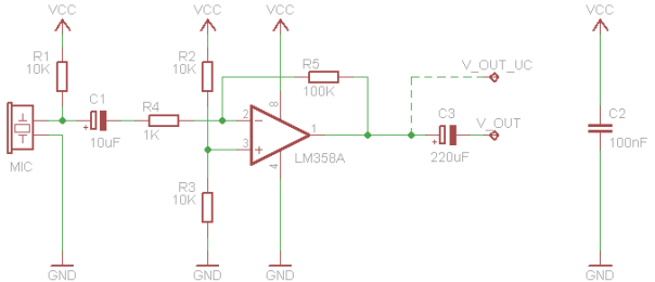
Now it’s back to making a boost circuit for the microphone, I looked around for a low cost op-amp and found the LMV358 which is just like the LM358 and it’s rail to rail. I found an LM358 op-amp inverting circuit which we’ll use to start off with (shown above). I firstly tried a non-inverting opamp configuration but it didn’t turn out to be as good as the inverting one above. The configuration above boosts the microphone’s output (which is AC coupled) by 100x and the 10K/10K divider on the non-inverting side keeps the opamp’s output at half of VCC so that when sounds are produced there will be an AC waveform (e.g with VCC/2 being 2.5V, we could get a waveform that goes 1.5V to 3.5V) just before the 220uF capacitor.
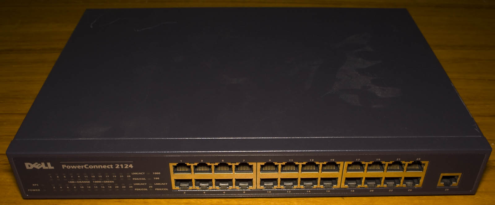
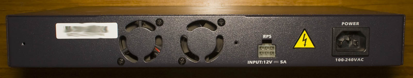
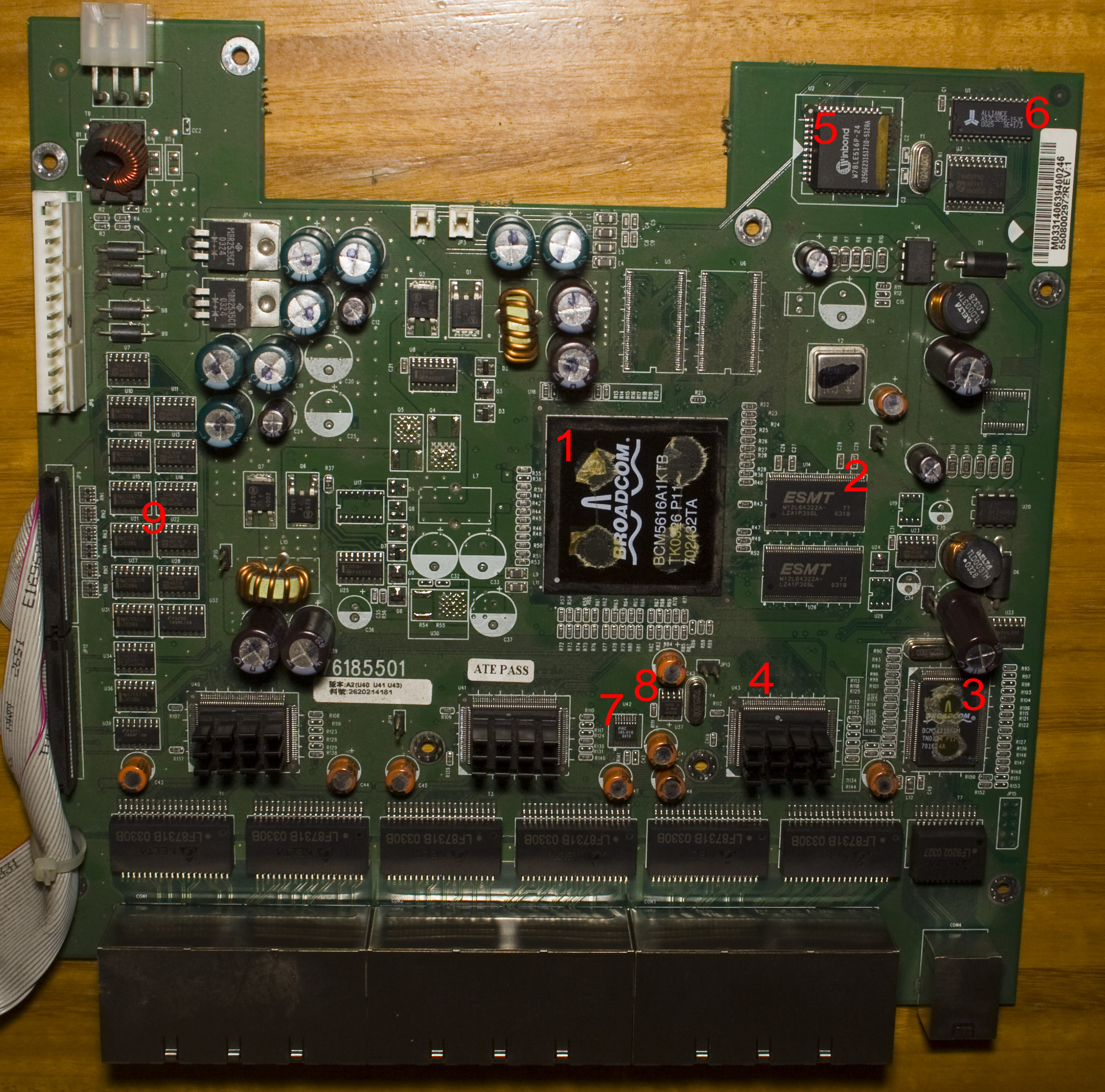
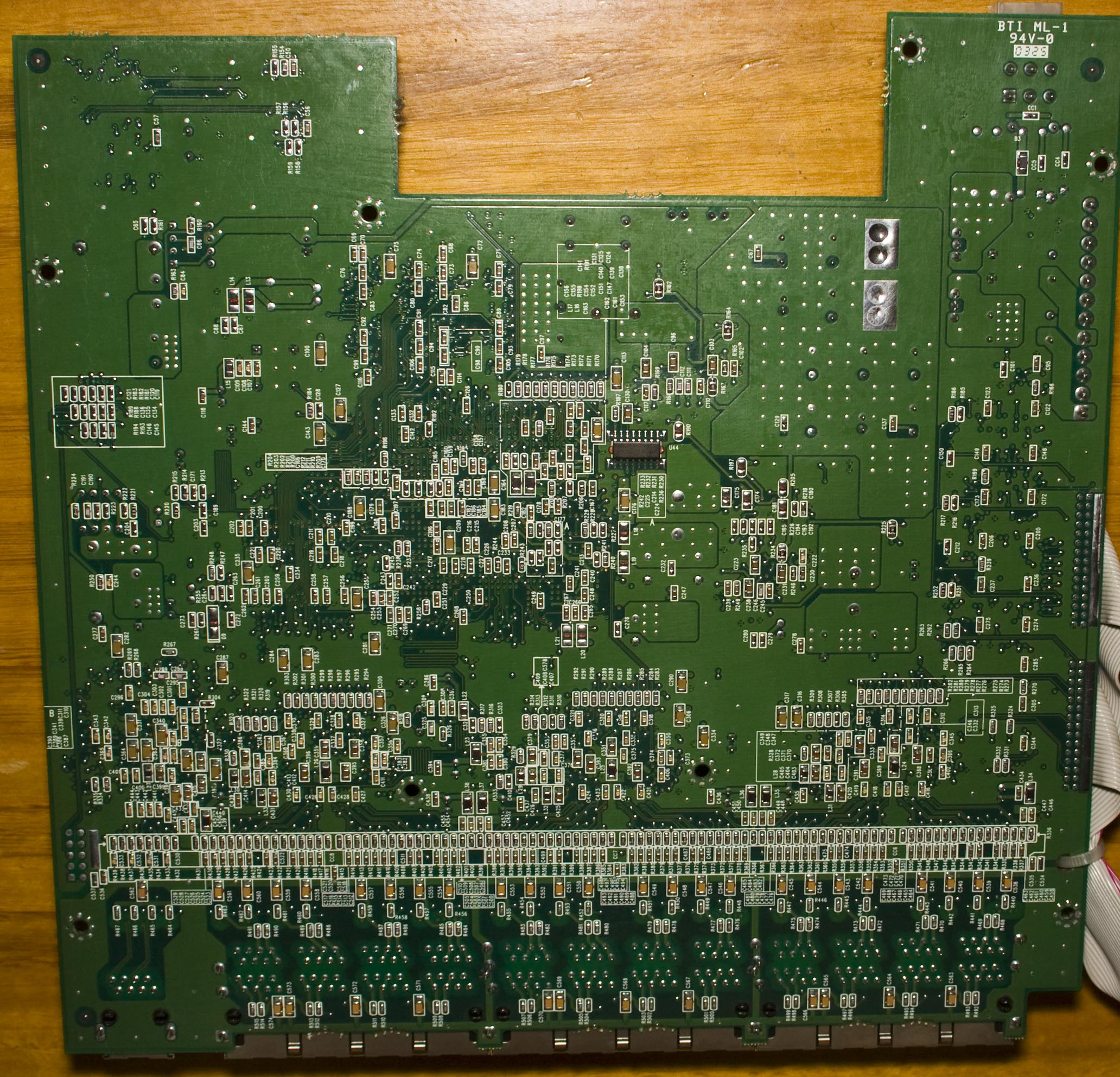
Today we’ll be taking a look at the Dell Power Connect 2124, a 24 Port 10/100 Switch with 1Gbit uplink. It’s got the capability of a redundant power supply and has 2 fans on the back, it’s a fairly old switch dated back to 2003.
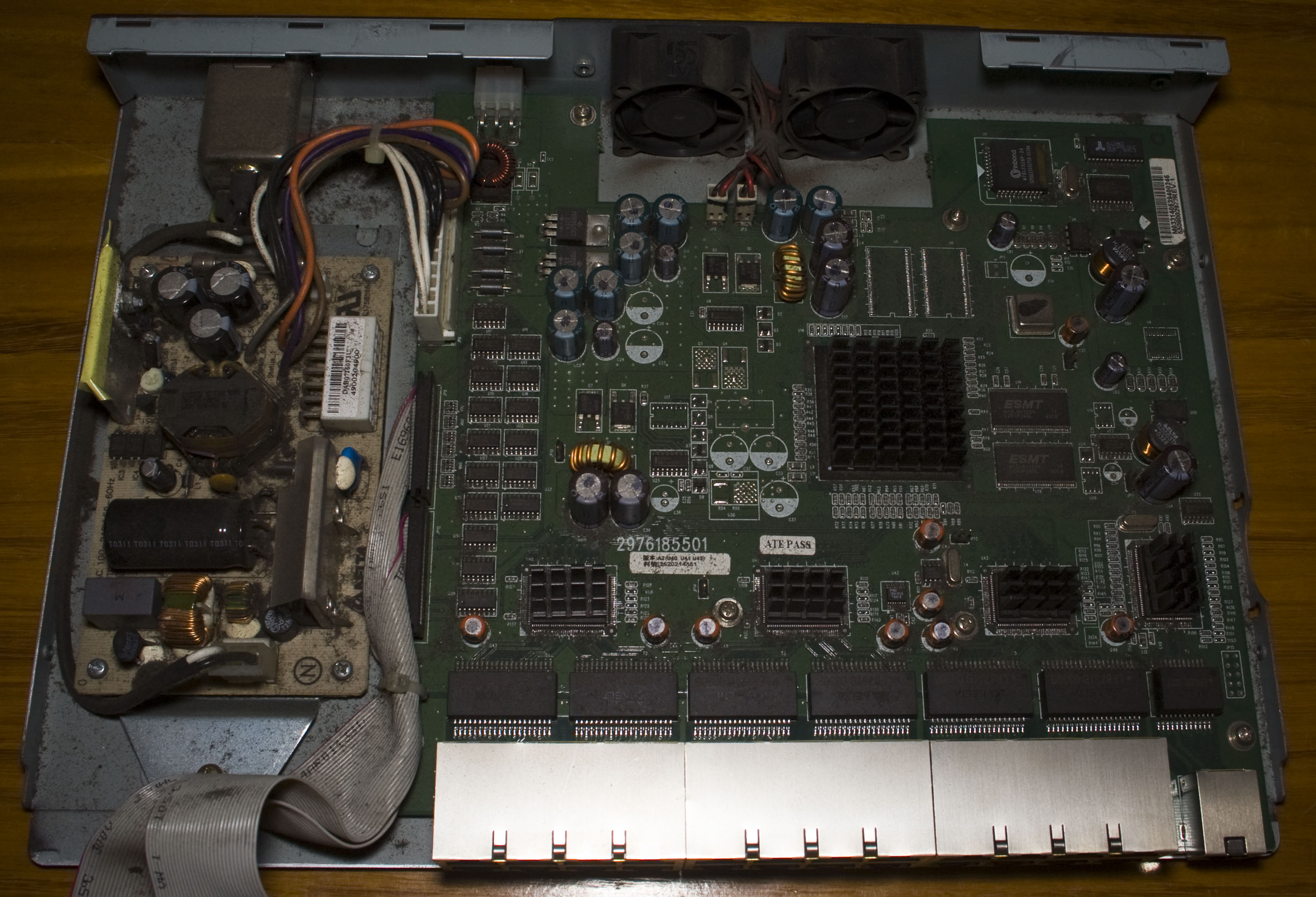
A few screws later and we’re in.
It’s a pretty dusty unit, we’ve got our power supply on the left which gives out 12V at 4.5A that connects to our main board and from the main board we have some cables running to the front panel. They’ve cut the board a little bit around fans to allow for better air flow.
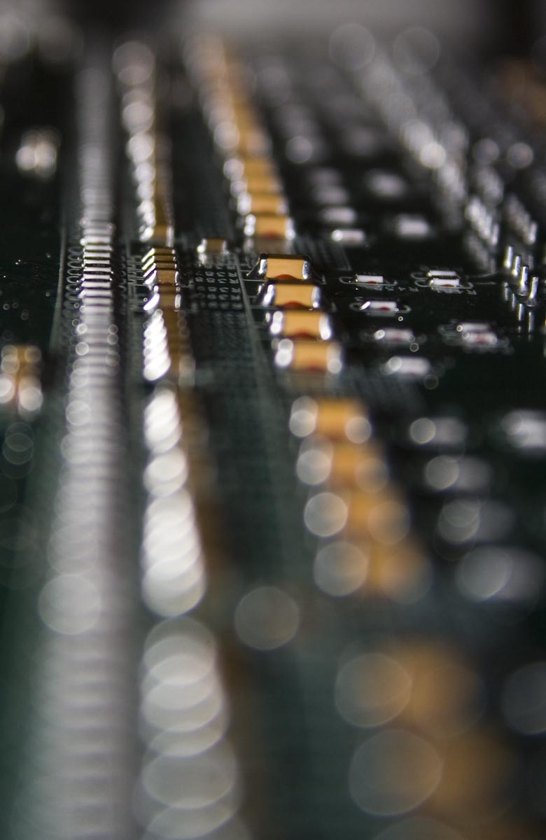
We’ve got a pretty large Broadcom chip in the middle that was under a heatsink – probably one of the largest I’ve ever seen and there’s heatsinks on each Broadcom PHY chip. If you look closely you can see the capacitor on the bottom right hasn’t been soldered down properly and the inductors nearby are a little like that too. There’s a whole heap of 74 series logic on the left which go off to the front panel. On the bottom we’ve got a fair few passives and a nice looking line of them too.
As this is my 200th post (excludes some posts which I didn’t count), I thought I would do something just for fun/just because I can 🙂
I acquired have 6 loud fans from a server a little while back and have been trying to figure out what to do with them so I’ve built a kind of wind tunnel by using a cardboard box to mount the fans, bubble wrap with some cardboard for support and some bubble wrap on the top to seal most of it off (would have been nice if it was all see through from the outside).
Now add some small pieces of paper and we have a little tornado, it works but the papers do settle down the bottom most of the time.
Over the years I have collected hard drives, most of them a failing and were going to be thrown out but I kept them and thought what would it sound like for all of them to power up at once?
Well I’ve got 40 hard drives on 5 ATX power supplies (it was 4 before but 1 was too overloaded when starting up), so now we know!
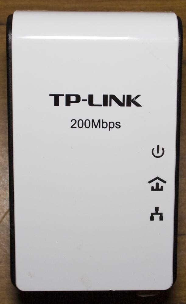
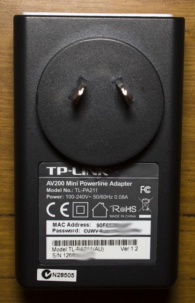
Today we’ll be taking a look at the TP-Link 200Mbps Mini Powerline Adapter (TL-PA211), an ethernet over power (EOP) device which won’t power up – this is the second one of these that has had power up issues.
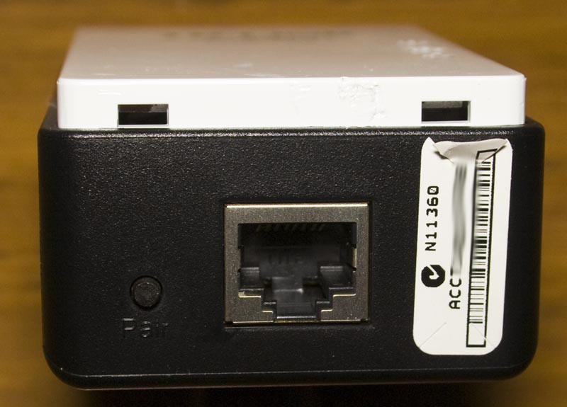
One screw later under the label and we’re in.
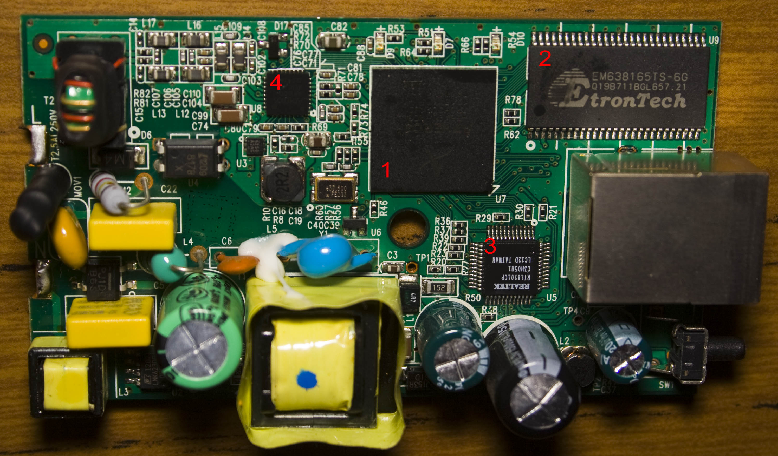
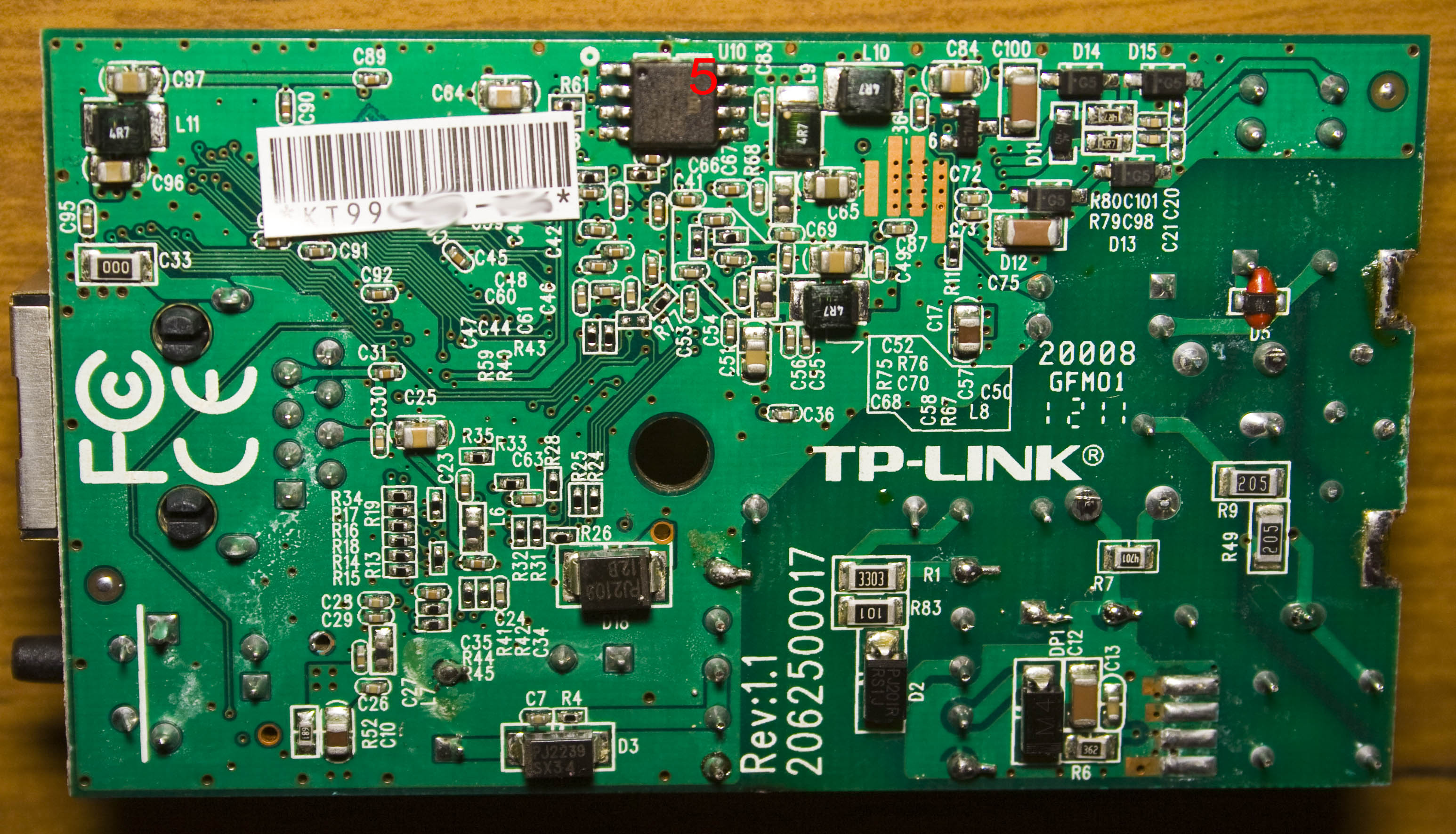
We’ve got the AC inputs on the left which are soldered on to the tabs, after unsoldering them the board pops out. There are a few heatpads on the top cover and the date code is 2012/11th week.
For the input power side of things we’ve got a Power Integrations LNK623DG AC to DC converter which can output up to 6.5W and this IC eliminates the need for an opto-isolator.
AdvanceVGA – Play your GBA on the big screen! Swap out the LCD for our board, solder some wires, connect 5V USB and VGA and you’re ready to go.
GBxCart RW allows you to backup GB/GBC/GBA ROMs, save or restore game saves and re-write supported flash carts. Mini RW option available for GB/GBC only.
Wireless Gameboy Controller – Use your Gameboy, mGB, GBC, GBA, GBA SP, GB Micro, NDS and NDS Lite as a wireless controller on Windows, Linux, Raspberry Pi, etc, and on your NES, SNES, N64, Gamecube and Wii.