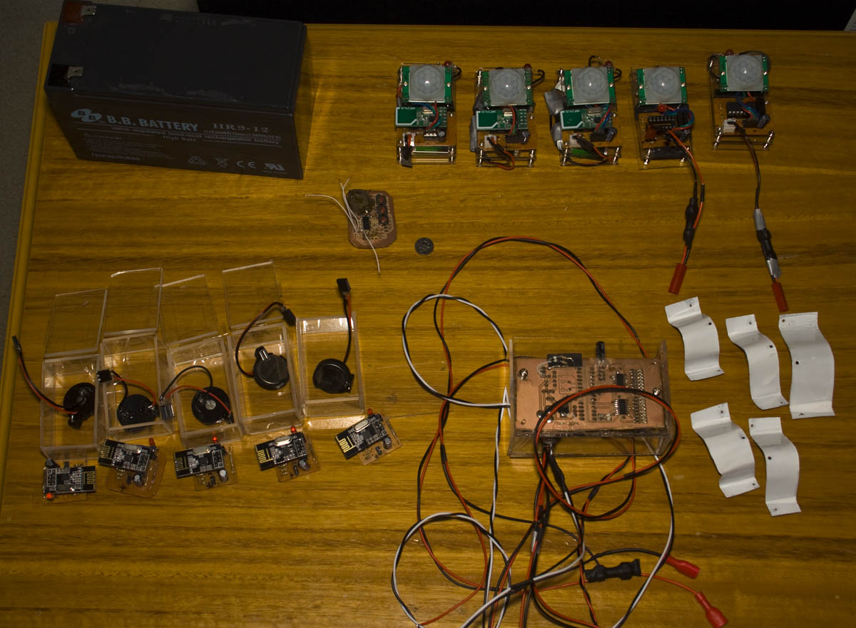
From our previous post, we made a small number of changes and started building acrylic cases/mounts for some of our boards. This time the cases/mounts have been build, a few more smaller changes and add in the SMS capability.
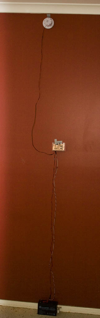
Here’s how everything looks at the moment – ready for deployment. I’ve got cases for the PIR, door sensors and the alarm system server which I’m planning to mount to the wall, connect the leads to the battery/adapter on the ground and the siren near the ceiling.
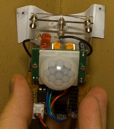
One problem that I’ve been able to find a simple solution to is how to mount the PIR on the corner of the wall like my current alarm system does. I’ve found that a 0.5mm aluminum sheet is flexible enough to cut with tin snips, mold into a U shape and it will keep it’s shape.
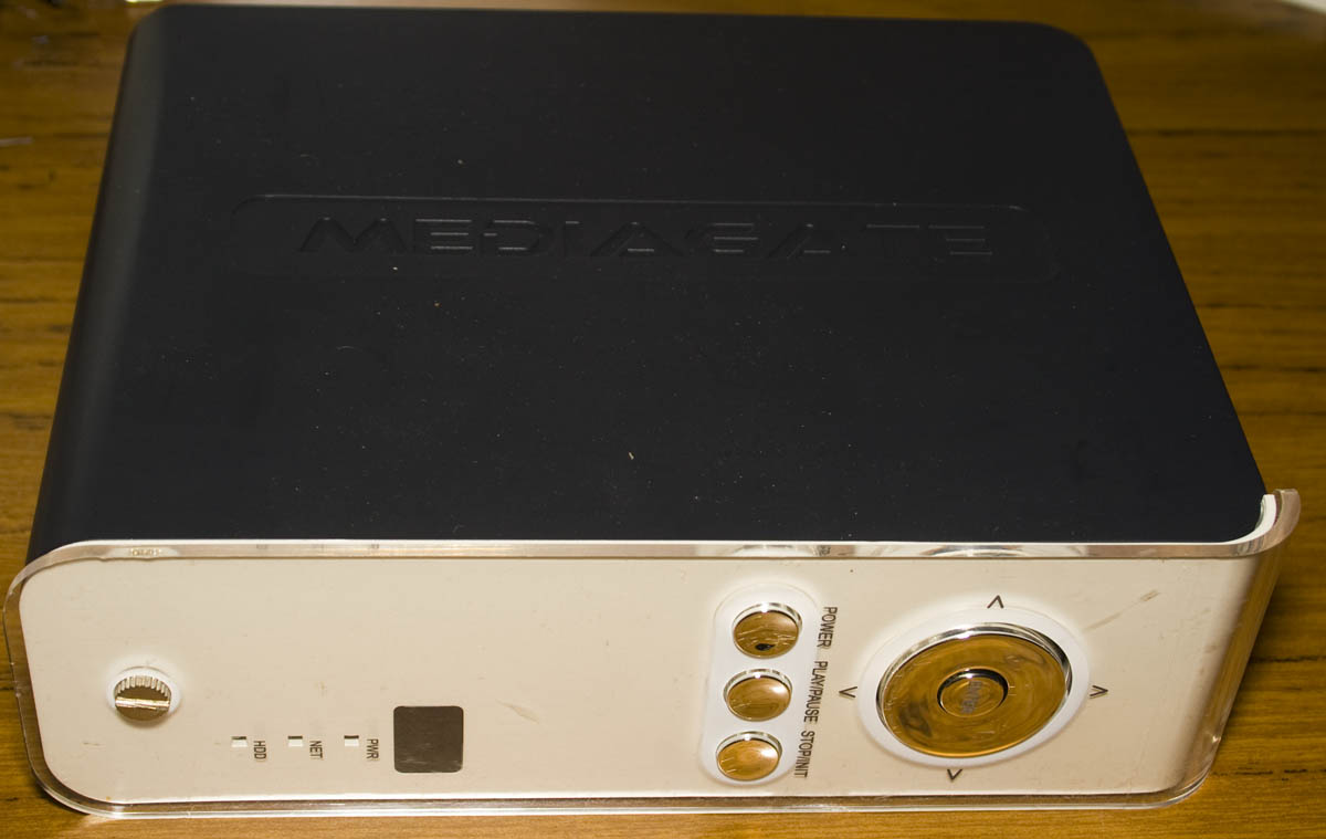
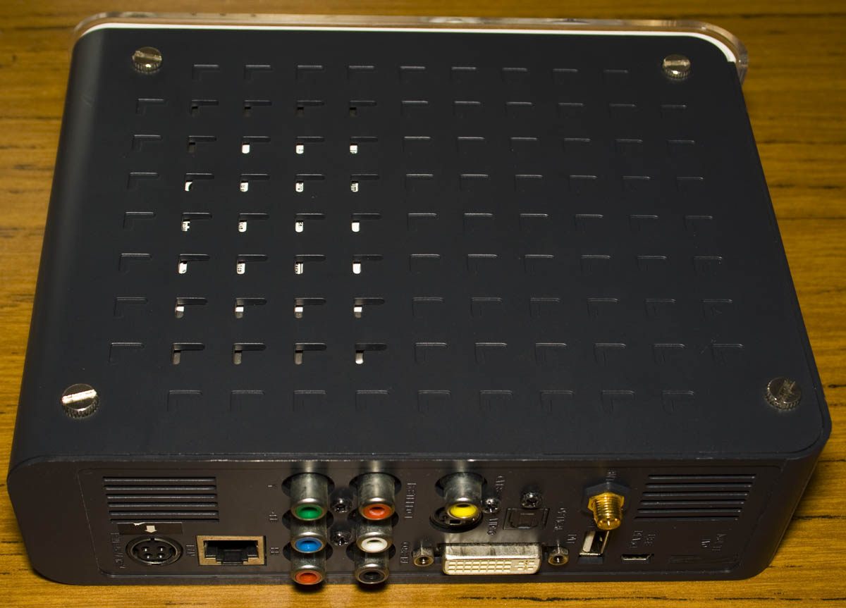
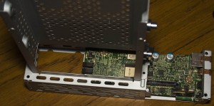
Today we’ll be taking a look at the MG-350HD Media Centre which is as it says, is a media center with Wifi/LAN, a 3.5″ IDE hard drive, USB with lots of outputs including component/composite/DVI/audio/optical so it’s pretty packed.
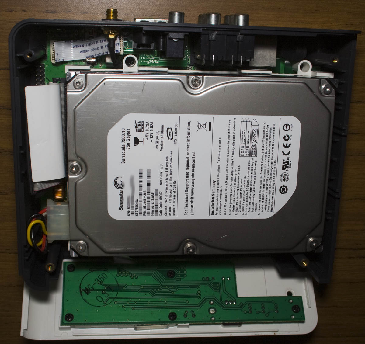
At first I wondered why it was so heavy, after opening it up there is a 750GB 3.5″ hard drive – so that’s why, it’s an IDE drive.
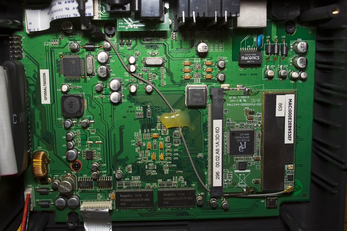
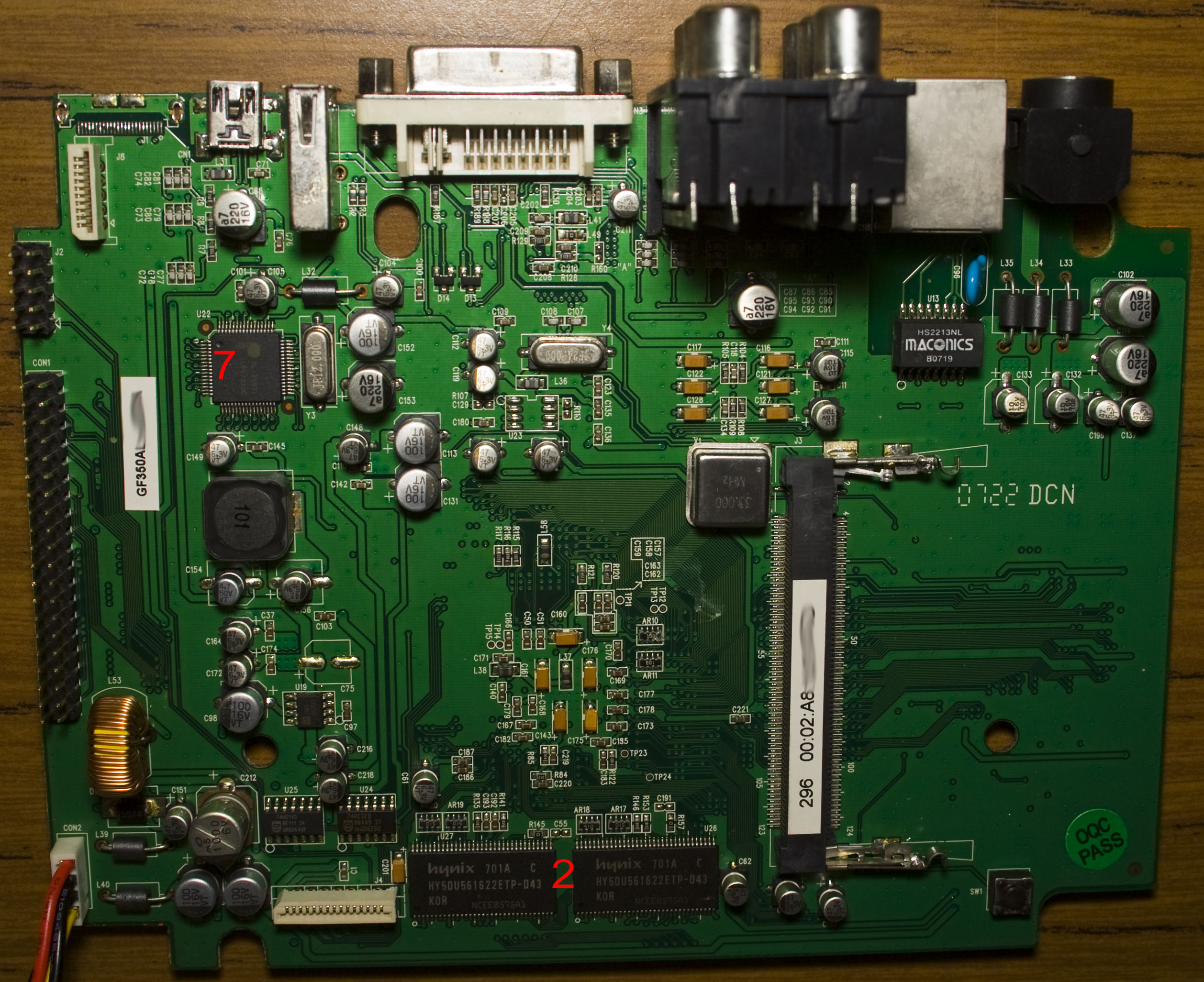
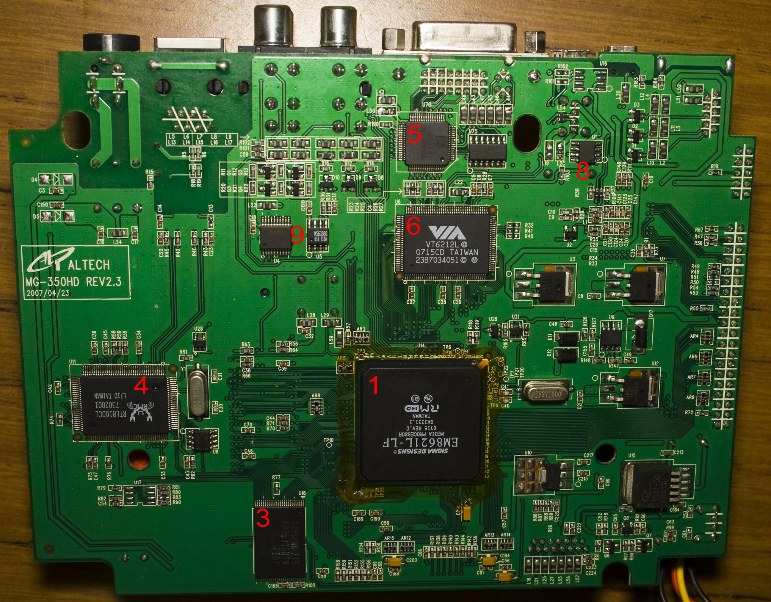
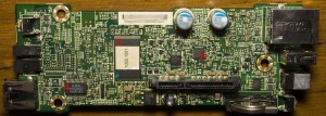
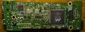
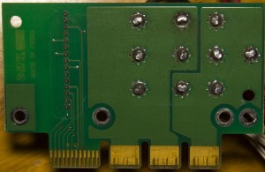
A few screws later and one screw under the wireless card, we’re in. We’ve got a fair amount of passives on the top with our Mini-PCI wireless card and on the bottom we’ve got chips with some regulators – 3x AZ1117 LDOs, 2x AP1605 SMPS and AP1501 SMPS. There’s flat flex cable connecting the optical/S-video and the front panel. PCB date code is 22nd week of 2007.
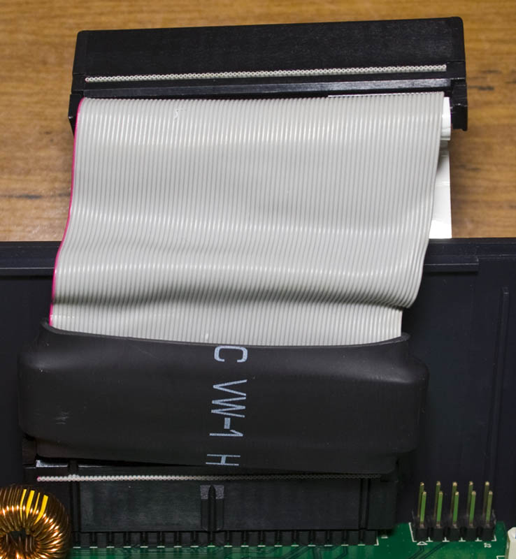
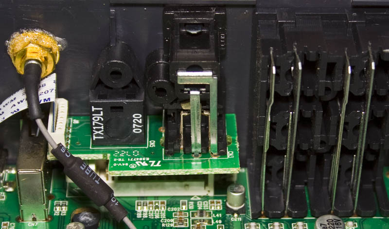
For the IDE cable, it looks like they have an ferrite core in heat shrink for EMI and it could be the same thing they are doing on the wireless antenna cable too. It’s interesting to see the video from the PCB to the connectors, the connecting conductors are pretty large.
A year or so ago I decided to make a smaller version of the Standalone Temperature/Voltage Logger which would only do temperature called the A25TTL which measured 17mm x 12mm. In this post, we’ll be updating the A25TTL to v1.1 so we can use any EEPROM, v2.0 so we can now also use an ATtiny13 and briefly show my new programming method for SMD ATtinys.
V1.1
At the time, I used the cheapest 512K EEPROM I could find (the ST M24512) however I found that not all EEPROM’s SCL/SDA lines acted the same and I had run the ADC a few times to determine if the logger was connected to the reader – not the best way to do this. I recently found that the M24512 EEPROM doubled in price so this was the main reason to update to v1.1 which makes the logger to set it’s pull up resistors on the SCL/SDA lines at boot which means that we can now use any EEPROM.
PORTB |= (1<<TWI_SDA_PIN) | (1<<TWI_SCL_PIN);

watchdogSleep(T1S); // Wait a little bit for things to settle

// Check if we powered up from the USB port
if (!(PINB & (1<<TWI_SCL_PIN))) {
	system_sleep(); // Sleep forever
}

PORTB &= ~(1<<TWI_SDA_PIN) | ~(1<<TWI_SCL_PIN);
...
This not only helps some EEPROMs reducing the current they draw but puts the ATtiny’s pins as inputs thus allowing the reader to pull SCL low. The logger waits 1 second, reads the SCL pin, if it’s low it goes to sleep otherwise it starts logging.
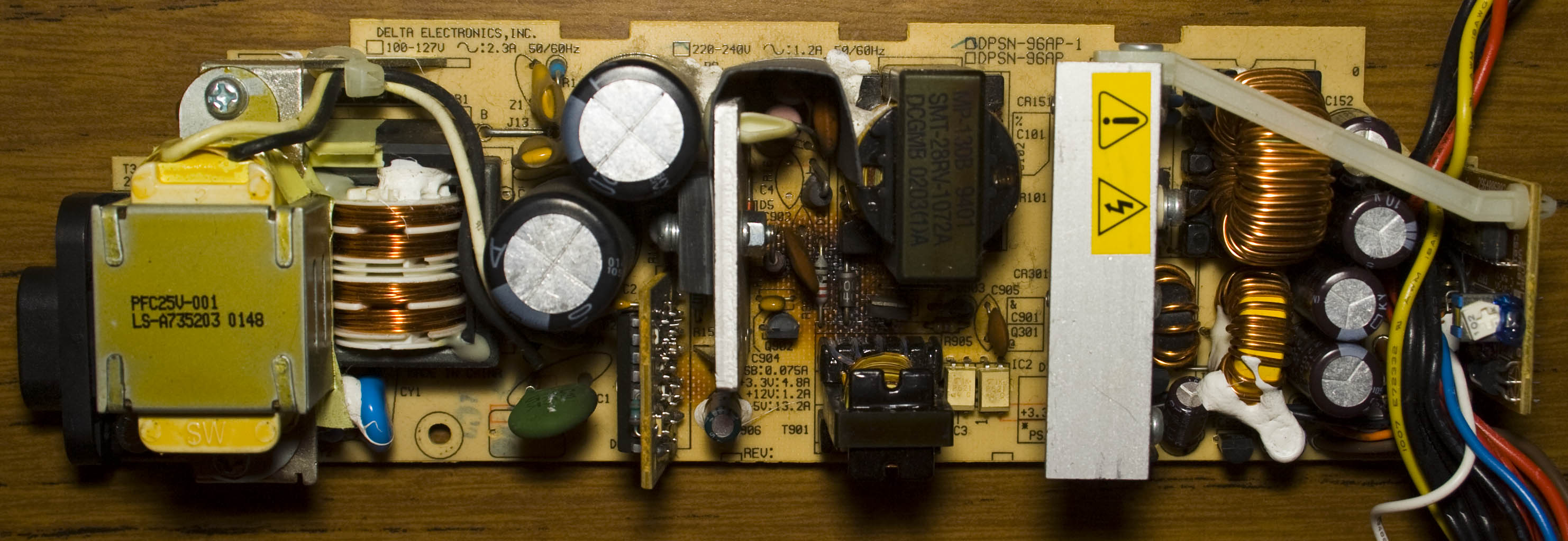
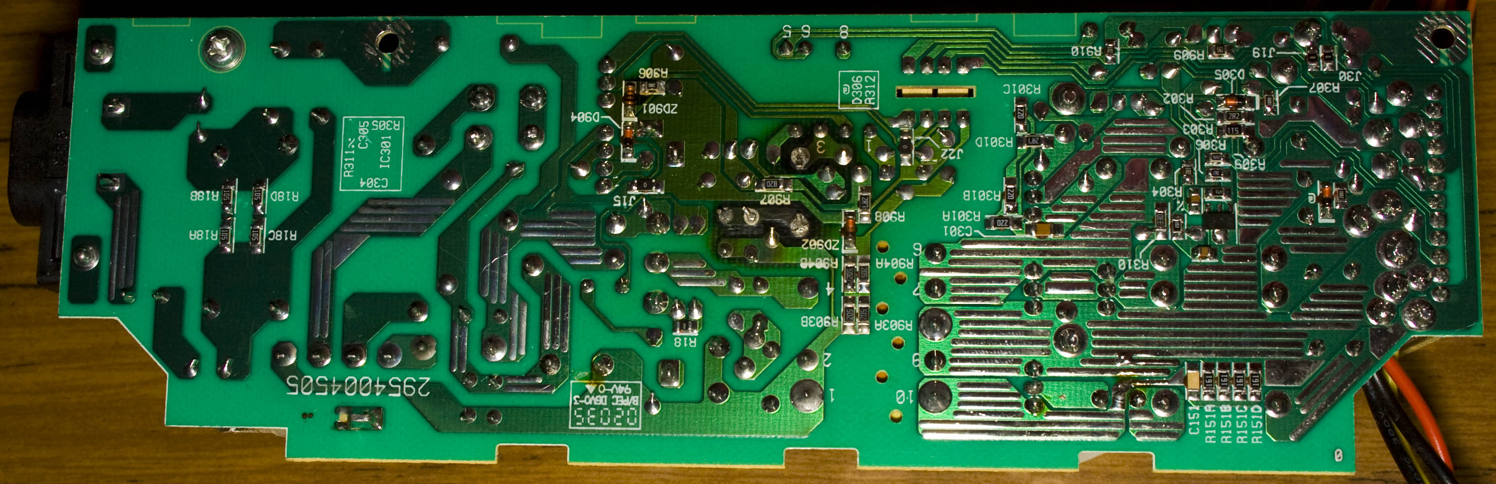
We have the original Xbox unit which is used infrequently and all of a sudden it wouldn’t power on, unplugged everything and measured no voltage on the outputs.
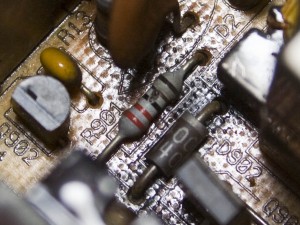
Naturally the problem would have to be on the power supply board, at quick inspection found black marks around a diode and resistor.
If you look more closely at the resistor you can see a slight mark which could mean it’s been damaged, I measured it in circuit and I was reading into the megaohms. I removed it from the circuit and it read open circuit, it looks to be 22 ohms.
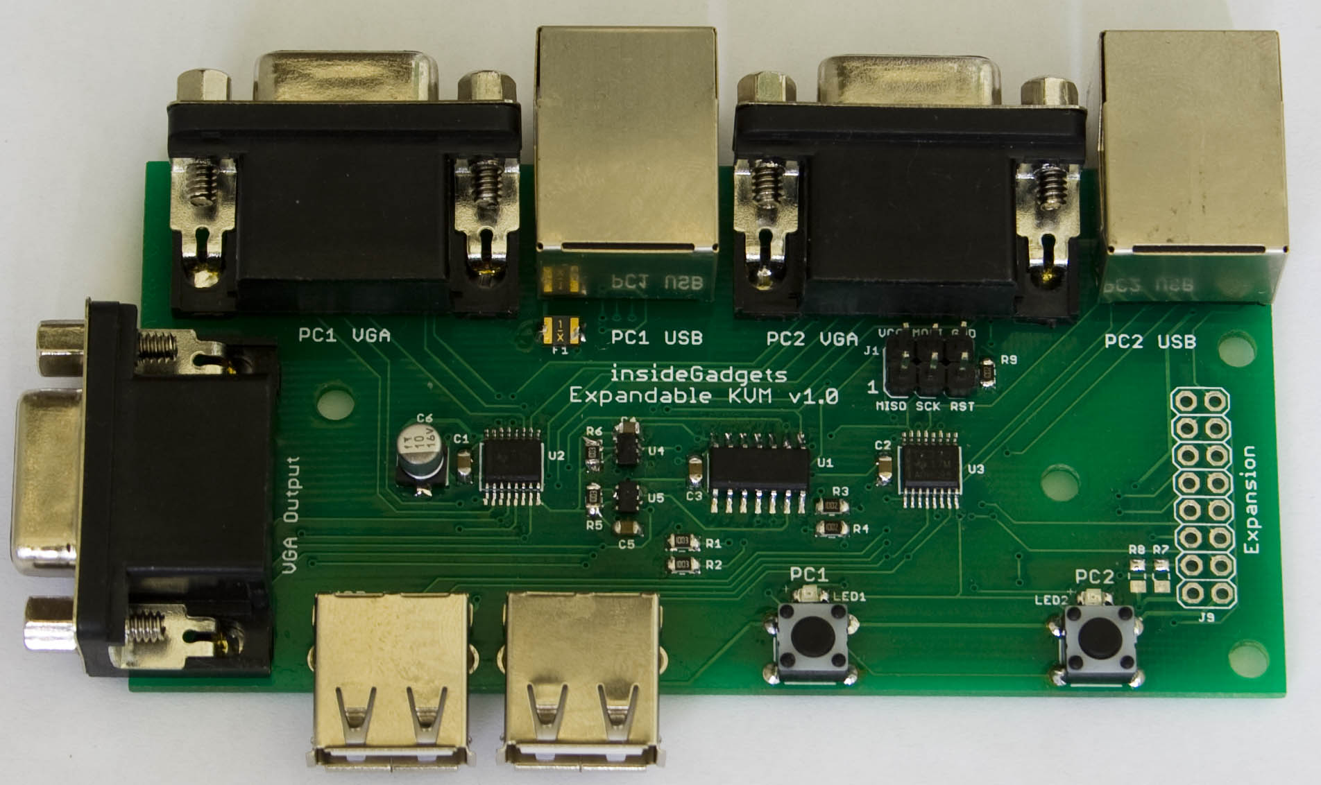
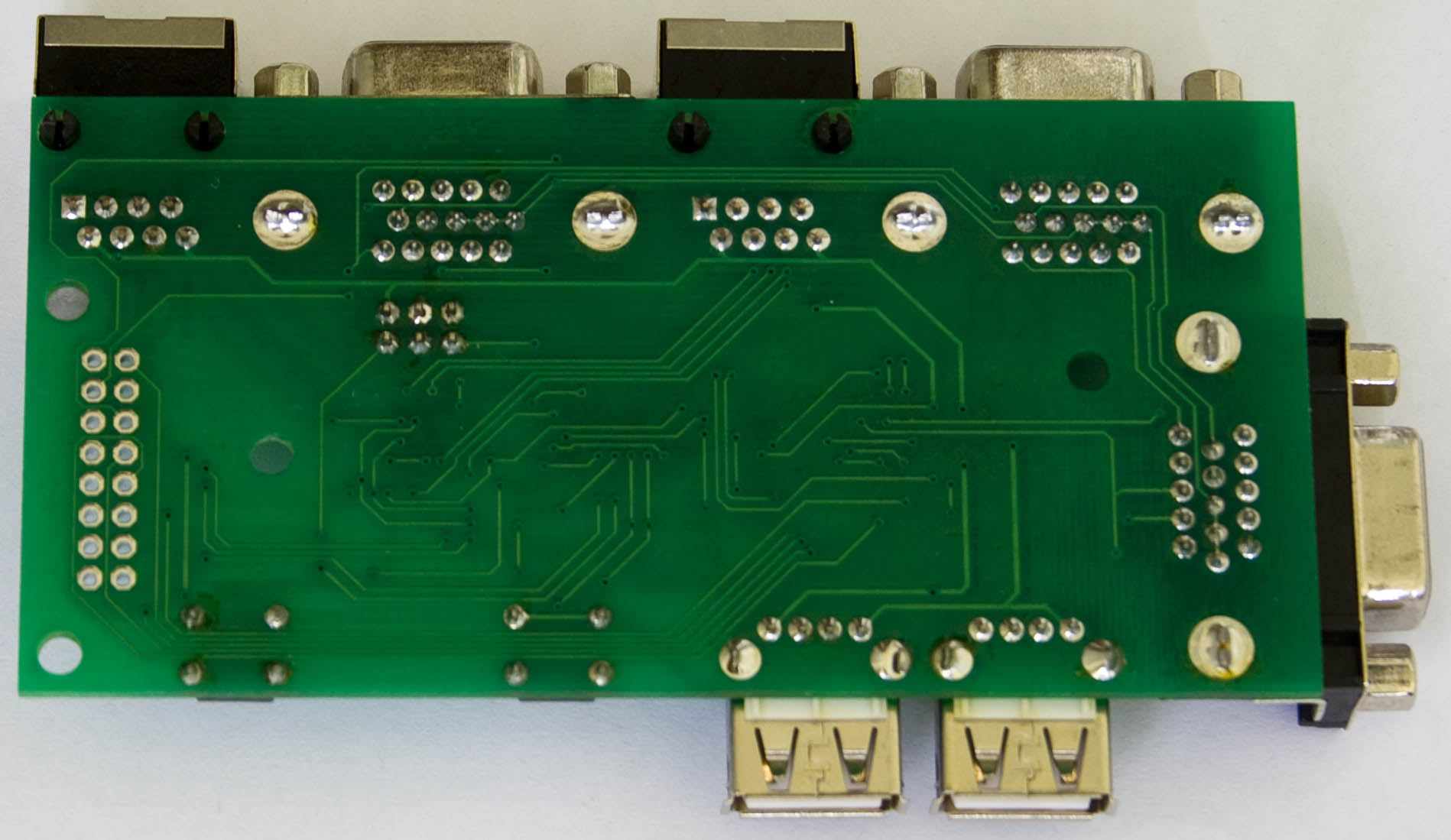
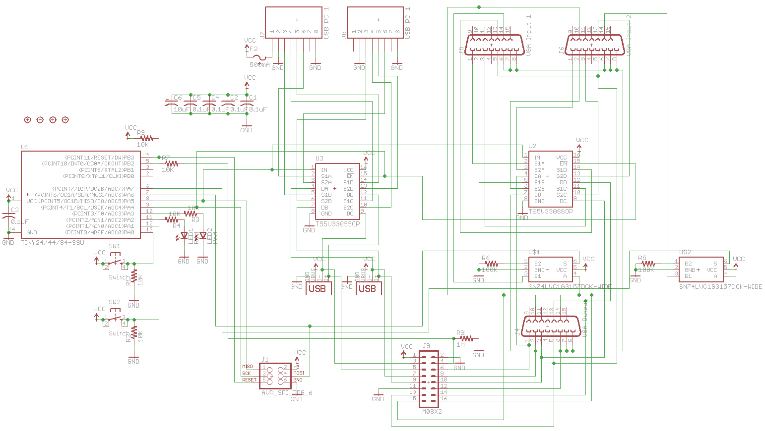
From our last part we made a PCB prototype and looked into how we could expand past two ports using 7400 series logic but in the end it’s easier to use an ATtiny to do this which we’ll take a look at this time plus the PCBs have arrived and I’ve made a case for it.
I went with the ATtiny24 which gives us enough pins to turn on both LEDs, monitor both switches, switch the enables and inputs high or low on our analog switches. After playing around with the expansion line concept which each ATtiny would be connected to, a 1M resistor to ground and 10K resistor to the ATtiny pin to protect it works well.
After combining both boards together into one, we have the schematic above. I’ve added the polyfuse, 2x of the SPDT analog switch with a 100K resistor to ground to make 1 side be high impedance, added a programming header, have 0.1uF capacitor on each IC and added a 10uF aluminum SMD capacitor to help with smoothing the power which would eventually go to the expansion boards and to also offer a little bit of voltage spike protection.
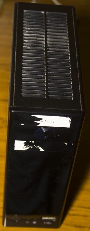
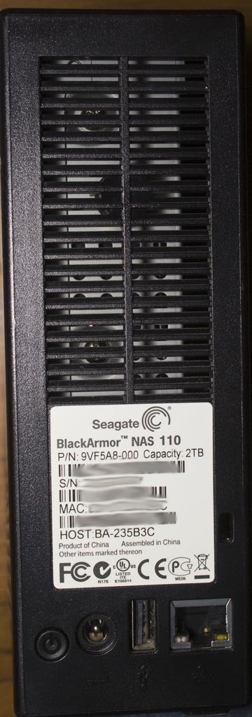
Today we’ll be taking a look at the Seagate BlackArmor NAS110 Network Attached Storage which has a single 3.5″ hard drive and 2x USB, it’s a pretty basic NAS. The date code is 2010/10th week.
Once the case comes off, you take the hard drive out and then slide out the PCB.
The top side of board looks like it has a lot going on but it’s more just all the part labels that make it seem that way.
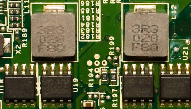
We’ve got a 3V coin cell for a RTC, 2x chips most likely to be SMPS with a mosfet chip labelled 4468 BA012X / 4712 BV0226 as they are near the inductors, an APL1085 3.3V / adjustable 3A LDO and an APL5930 3A LDO. Something small that stood out to me was an SMD LED which emits its light horizontally instead of vertically.
Ever since I built my 4 bay 3.5″ NAS using the Raspberry Pi which was placed inside a Netgear NV NAS enclosure, I’ve been wanting to make a single bay NAS with a 2.5″ drive to use as a small file server or for backups. I’ve decided that I’ll use it for remote backups in which I’ll use rsync over SSH from my linux server to backup some of my data at night.
(sneak peak)
Due to my use case, I’ll need to have it operating 24×7 and don’t really have a need for an LCD or even power button, so it will be a minimalistic design. The Raspberry Pi was purchased from Element14 / Newark and this time it has mounting holes which will make things more easier for us. In terms for the power supply, I’m able to re-use an existing 5V 2A supply but otherwise I could have used my SMPS.
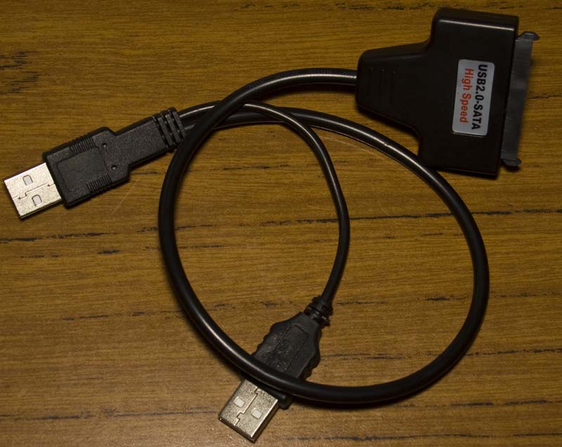
The SATA to USB adapter that I bought from Ebay was larger than I wanted so it’s time to make it smaller.
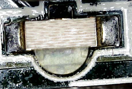
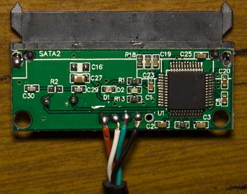
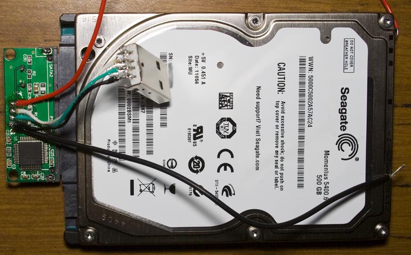
I went ahead, opened it up, shortened the USB cables, separated the power cable out (as I don’t want the Pi itself to power it), re-soldered the wires to a USB connector I had – it’s now more compact. As a side effect, this SATA adapter has quite a bright blue LED which illuminates through the acrylic case which gives it some colour. Just using a spare 500GB hard drive whilst testing.
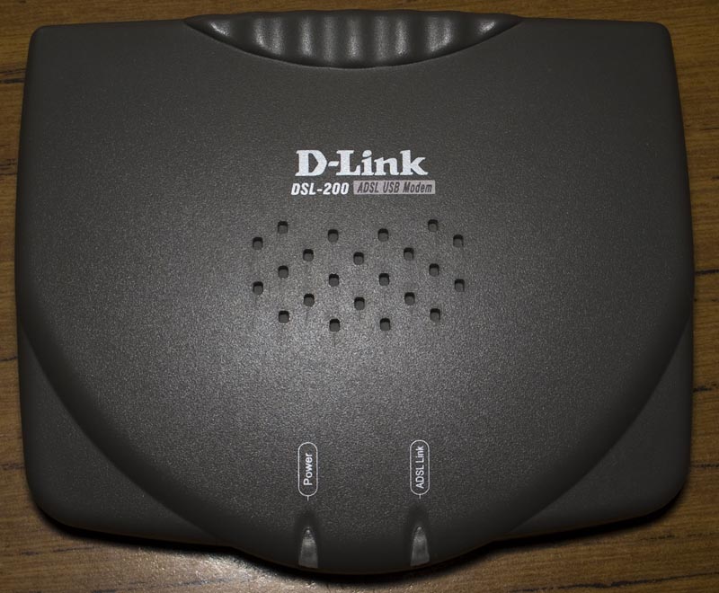
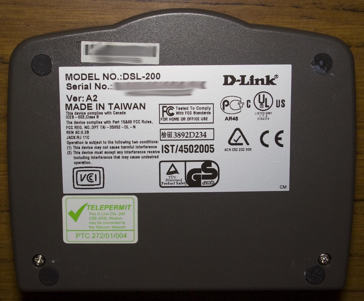
Today we’ll be taking a look at the D-Link DSL-200 ADSL USB Modem device which is the first ADSL modem I had back when we got ADSL in 2002, it’s a USB powered modem. The date code is 2002/27th week.
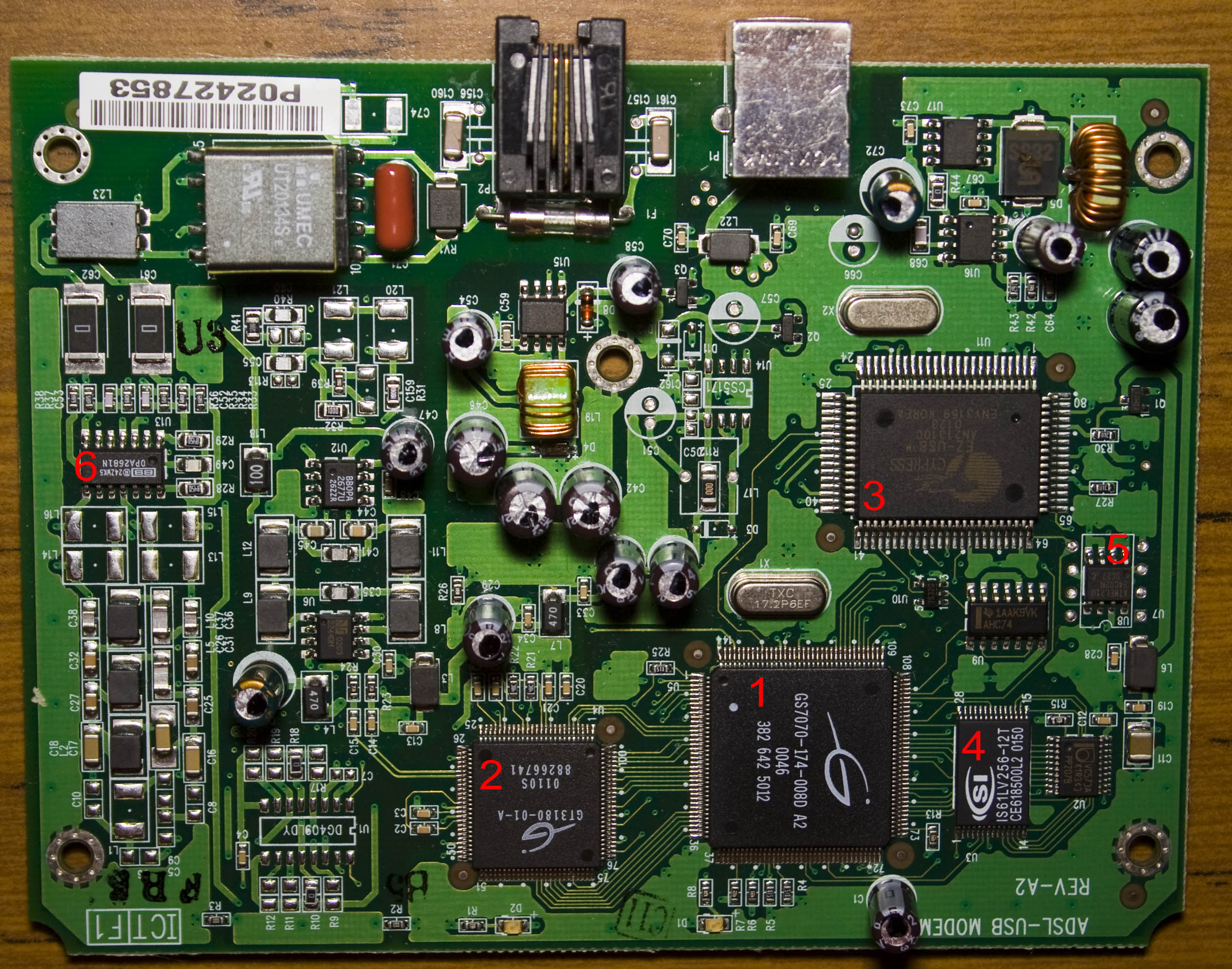
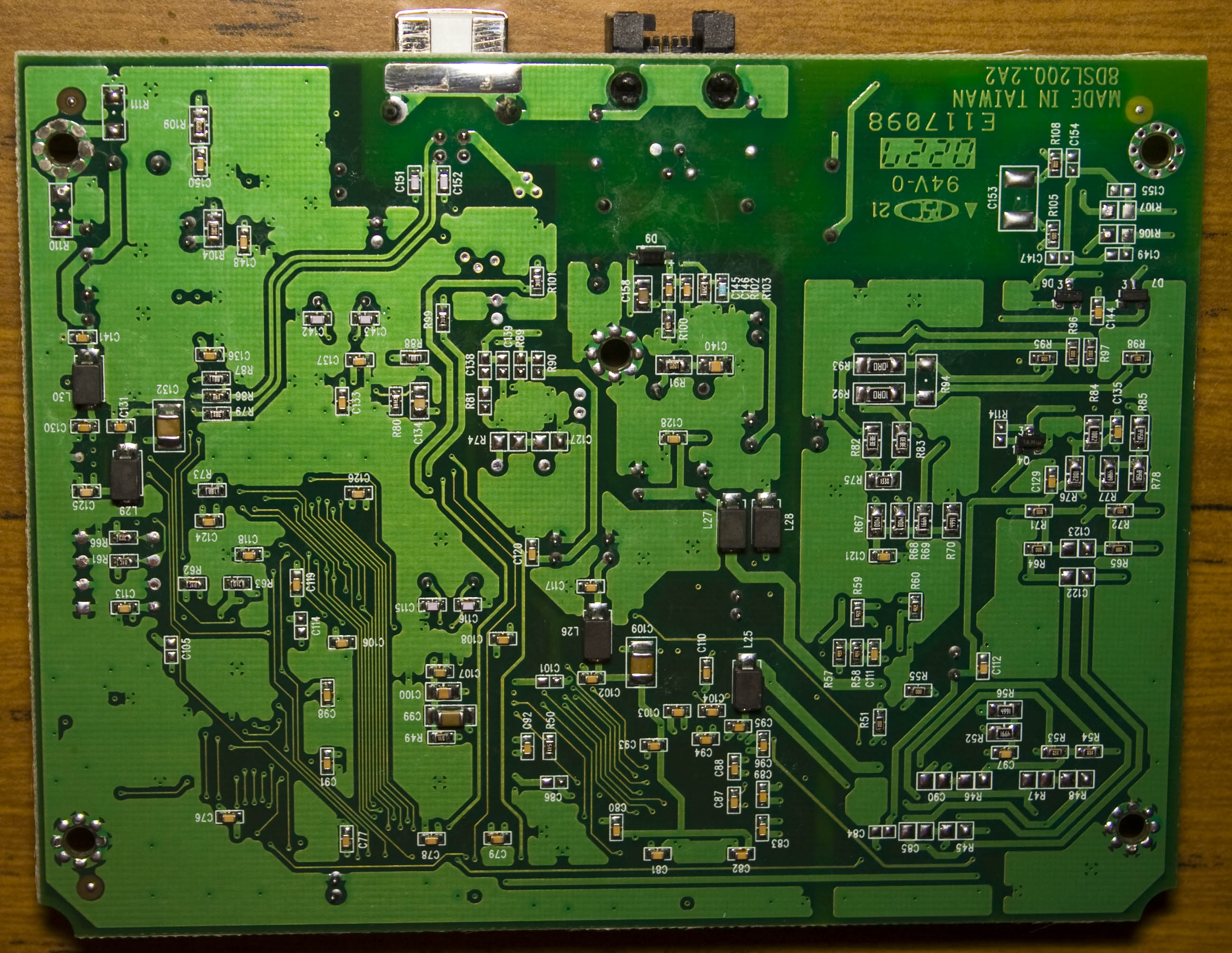
The top and bottom board have quite a bit of inductors, the top right side of the board has quite a few capacitor all bunched together and we’ve got a fair amount of chips. We have a On Semi 51031 SMPS with a IRF7416 P mosfet to form part of the SMPS and there’s a 5171E boost regulator likely to be for the ADSL side (in the middle of the board).
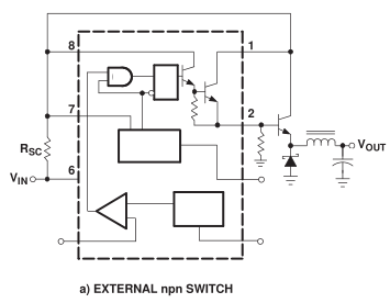
From our last post we looked at adding a transistor to the MC34063 and eventually changed to a P mosfet although we had to use a pretty large heatsink to dissipate all the heat. I decided to revist this SMPS to see if we could improve it to generate less heat, as I might have a few projects that could possibly use 5V output and 12V+ input.
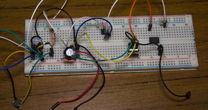
I decided to build the circuit with a NPN transistor – the TIP31 however with a small heatsink with 5V @ 0.37A, it rose up to 55C so I went back to a P mosfet. I began changing all the other parts – using different diodes, inductors, resistors however the P mosfet still got pretty hot even with a small heatsink.
Thinking that the MC34063 could be causing the issues itself, I went ahead and used an ATtiny to replicate what a little bit of SMPS would be doing – pulsing an output high and low for a specific duty cycle until I reached 5V. The heat was about the same as the MC34063 but just a little less as I didn’t compensate for the load reducing the voltage.
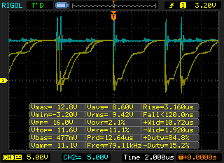
So it’s back to the IRF9540 P mosfet, after researching into it, it seems like the turn off time / capacitance is pretty important for our application, this mosfet has 1400pF input / 590pF output capacitance, 73ns rise time, 34ns turn off and 57ns fall time. On paper this mosfet seems good however as above we can see the turn off time is really 4us (yellow line, going low to high). Also there is an spike (blue) which I was able to soften down later a bit by adding a 470uF capacitor to the input VCC/GND (before I had 100uF).
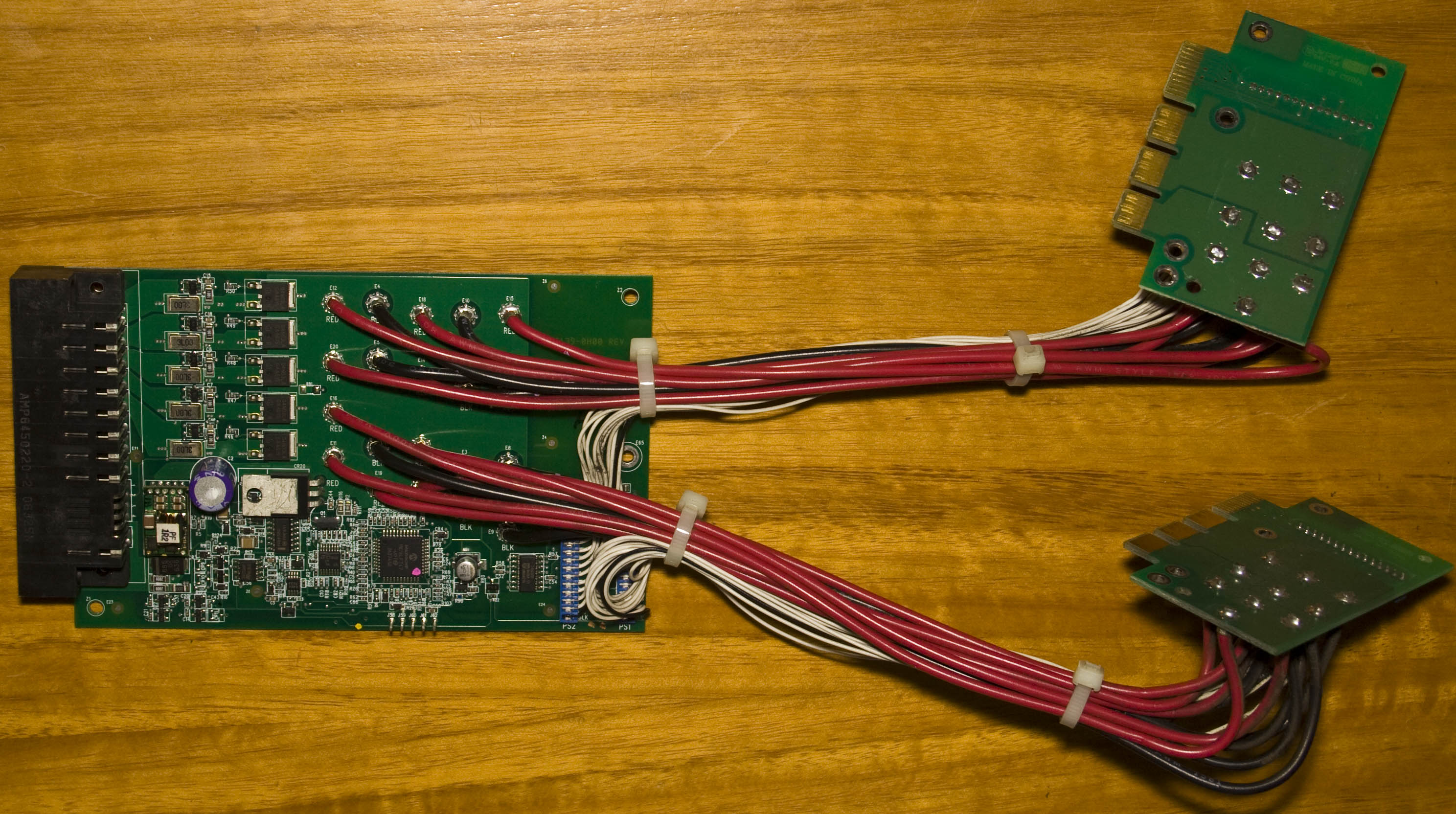
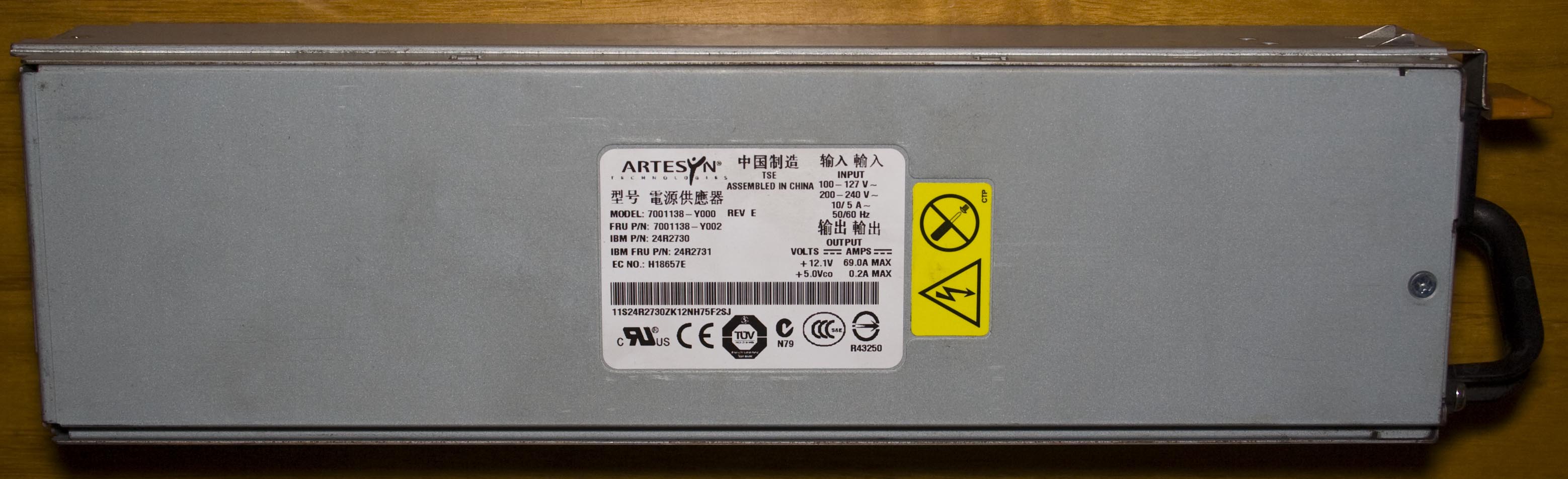
Today we’ll be taking a look at the IBM Server Redundant Power System (2006) board which was taken out of an IBM server, its purpose is to combine both power supplies into one and know when a power supply goes offline/online. The date code is 2006/46th week.
I was able to take both power supplies from the server which were rated at 12V at 69A which gives 828 watts which is unusual to have that much amps on the 12V rail and I would like to use each one independently of this RPS board which we’ll also look at.
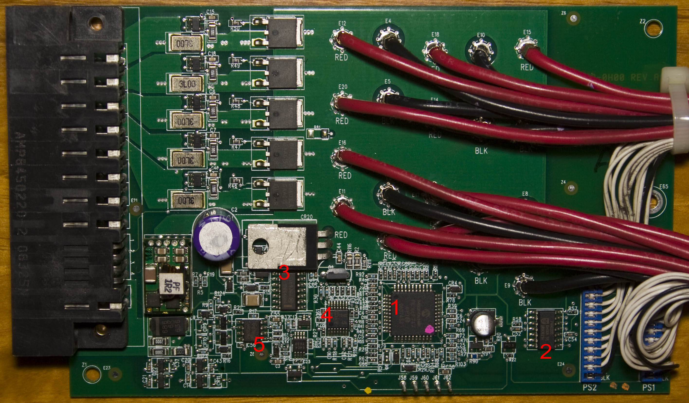
It’s a nice looking board and there are two sub-boards for the power supplies, all that’s being carried over is 12V on the thick red wires and some control lines too. We’ve got a little sub-board soldered on the main board too with two chips, some capacitors and an inductor, likely to be a SMPS. Another component that stands out is the TO220 part tipped horizontally to keep it low profile, usually you don’t see the metal part in the air like that. They’ve got a Infineon 04N03LA N power transistor and current sense resistor for the 5x 12V rails to regulate how much current each rail receives.
AdvanceVGA – Play your GBA on the big screen! Swap out the LCD for our board, solder some wires, connect 5V USB and VGA and you’re ready to go.
GBxCart RW allows you to backup GB/GBC/GBA ROMs, save or restore game saves and re-write supported flash carts. Mini RW option available for GB/GBC only.
Wireless Gameboy Controller – Use your Gameboy, mGB, GBC, GBA, GBA SP, GB Micro, NDS and NDS Lite as a wireless controller on Windows, Linux, Raspberry Pi, etc, and on your NES, SNES, N64, Gamecube and Wii.