Posted in Teardowns on Nov 17th, 2017
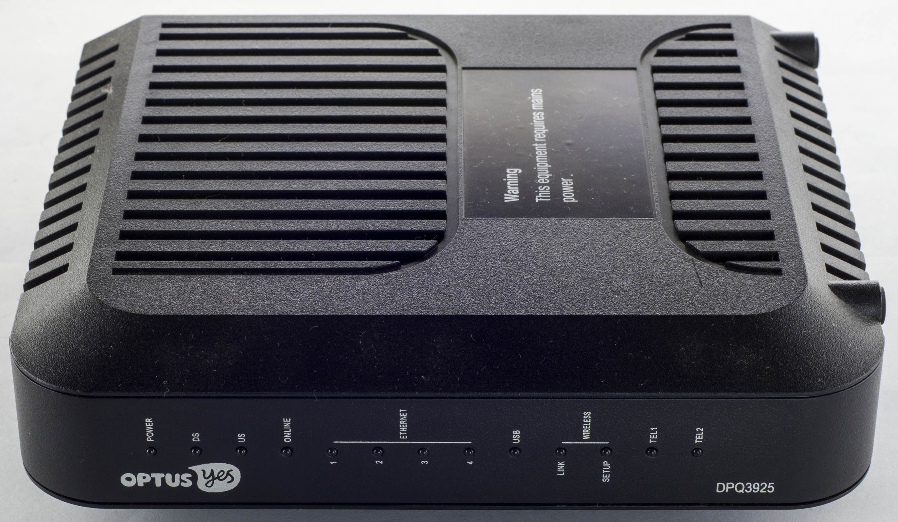
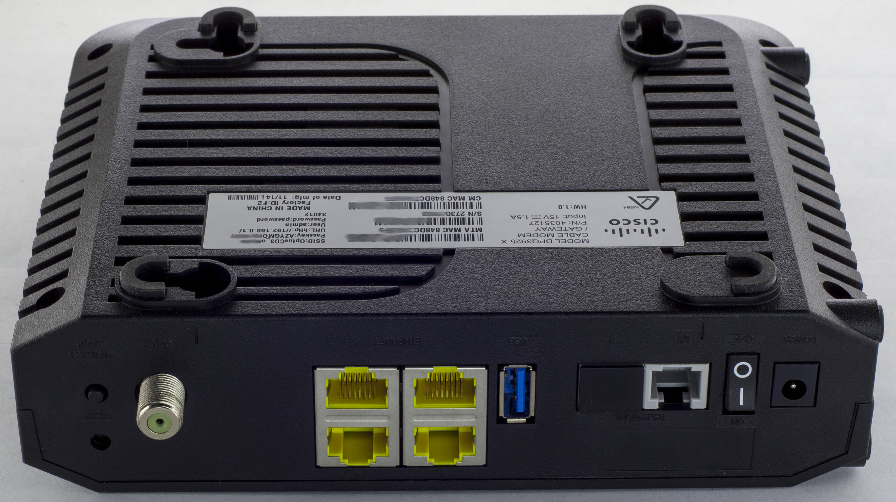
Today we’ll be taking a look at the Cisco DPQ3925-X Cable Modem / Gateway which is a cable modem with 4x Gigabit Ethernet ports, 802.11n Wifi, USB port and 2 analog phone ports.
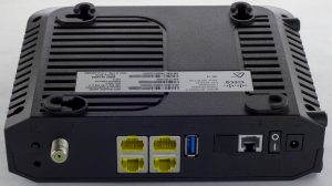
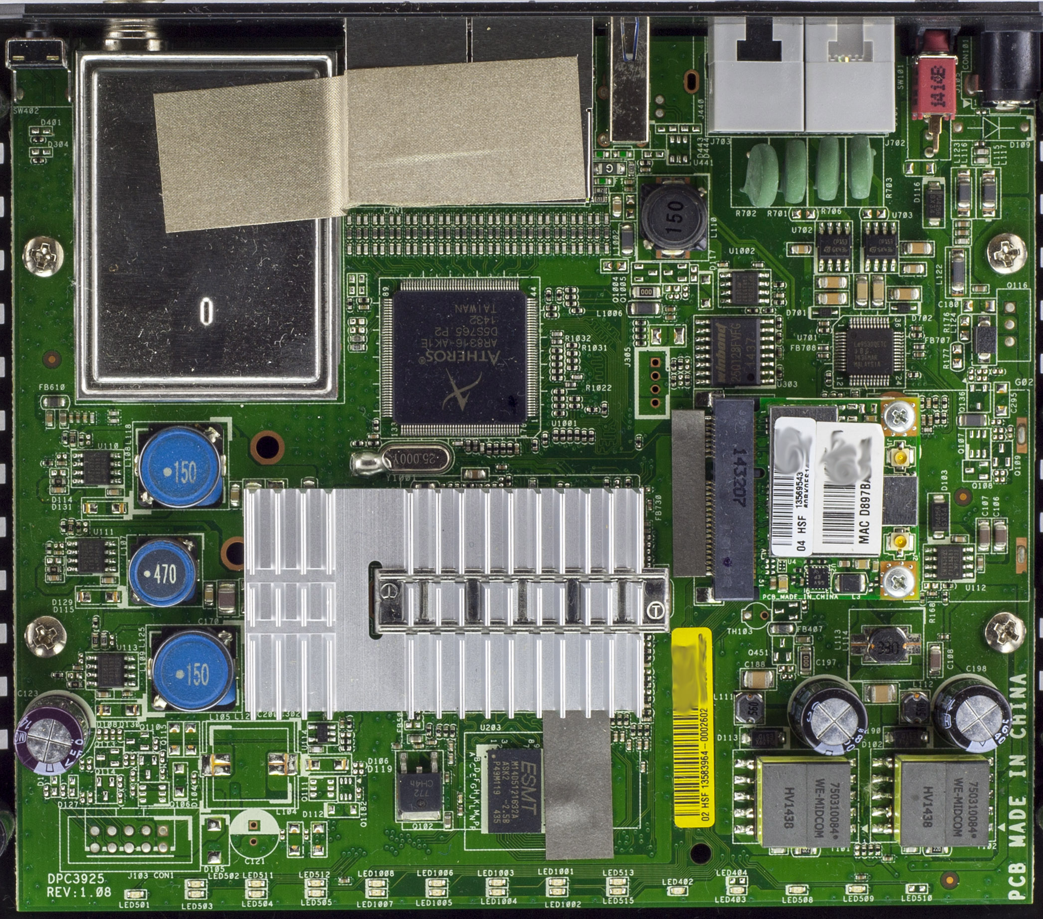
4 screws later and we’re in.
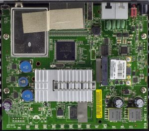

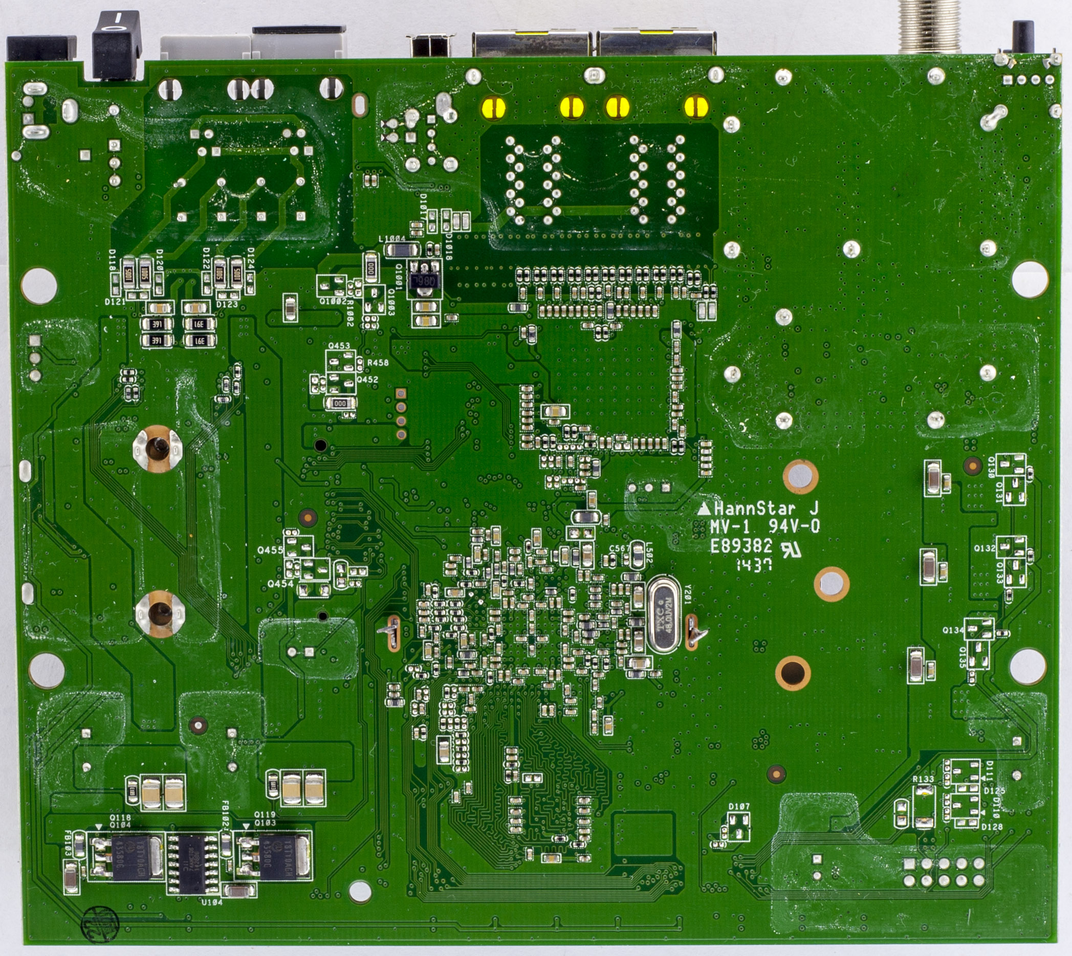
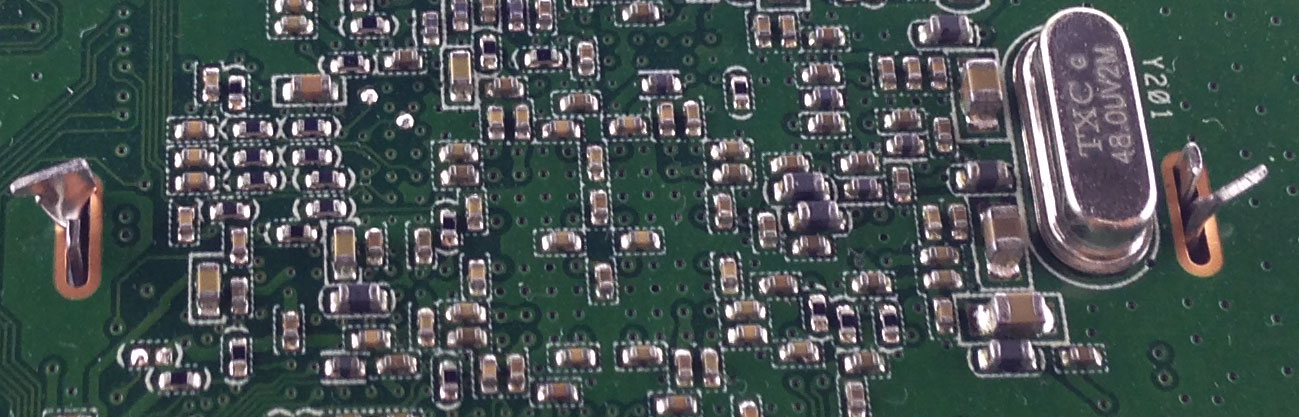
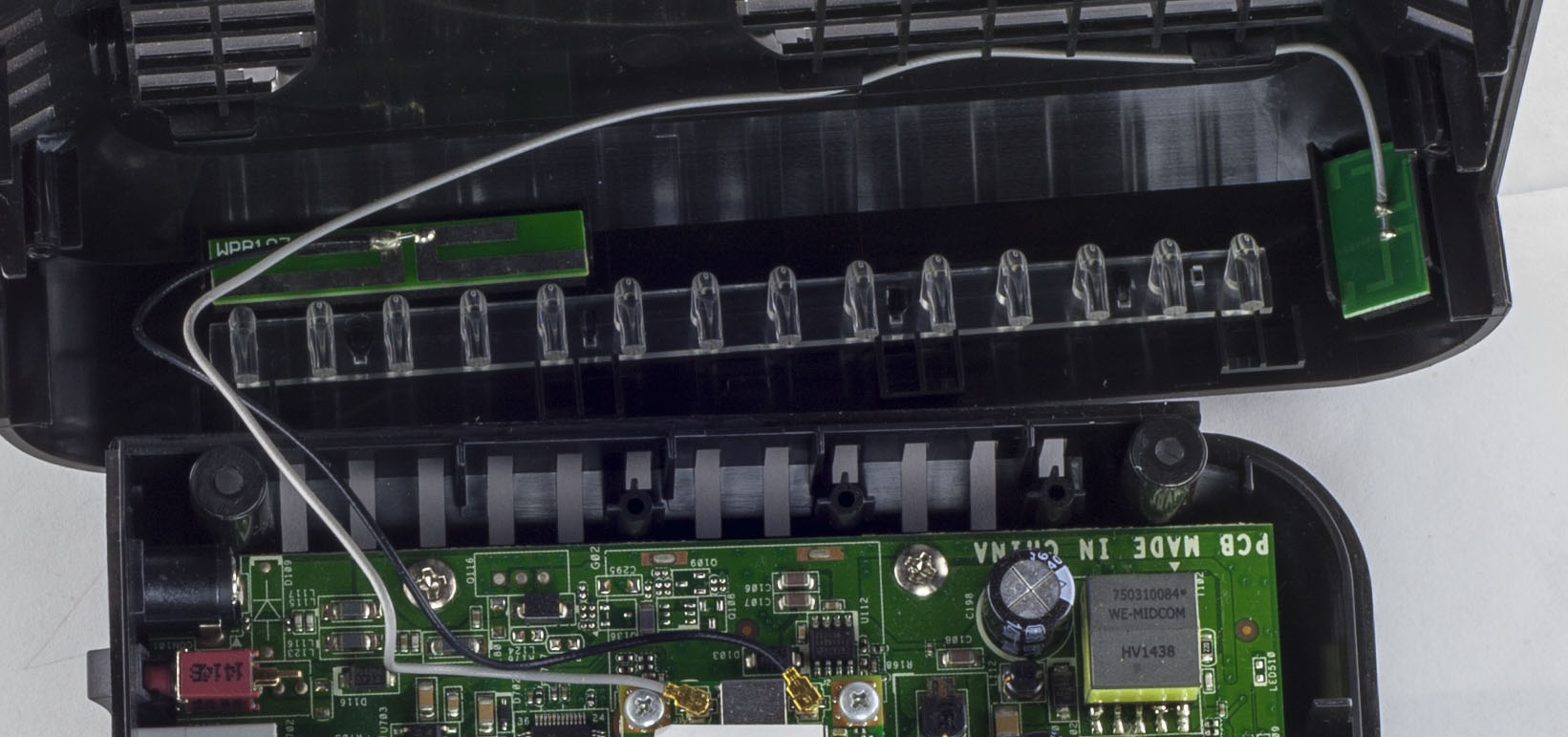
Looks like we have a 2 chip solution, one of them has a pretty large heatsink. There is a Mini-PCI Express Wifi adapter with dual antennas. There is an RF can for the cable input and some conductive tape connecting it to the ethernet ports which is a little odd as the ethernet shielding is grounded. We also have tape near the main processor going to the memory and another small piece right next to the Mini PCI Express connector, strange. PCB date code is 37th week of 2014.
The main heatsink isn’t soldered down, instead the legs are bent so it can’t go anywhere.

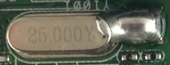
Something else that stands out is that we have a 25MHz crystal which the case was soldered to ground.
The 2 Wifi antennas are located in the front of case.
(more…)
Read Full Post »
Posted in Teardowns on Oct 6th, 2017
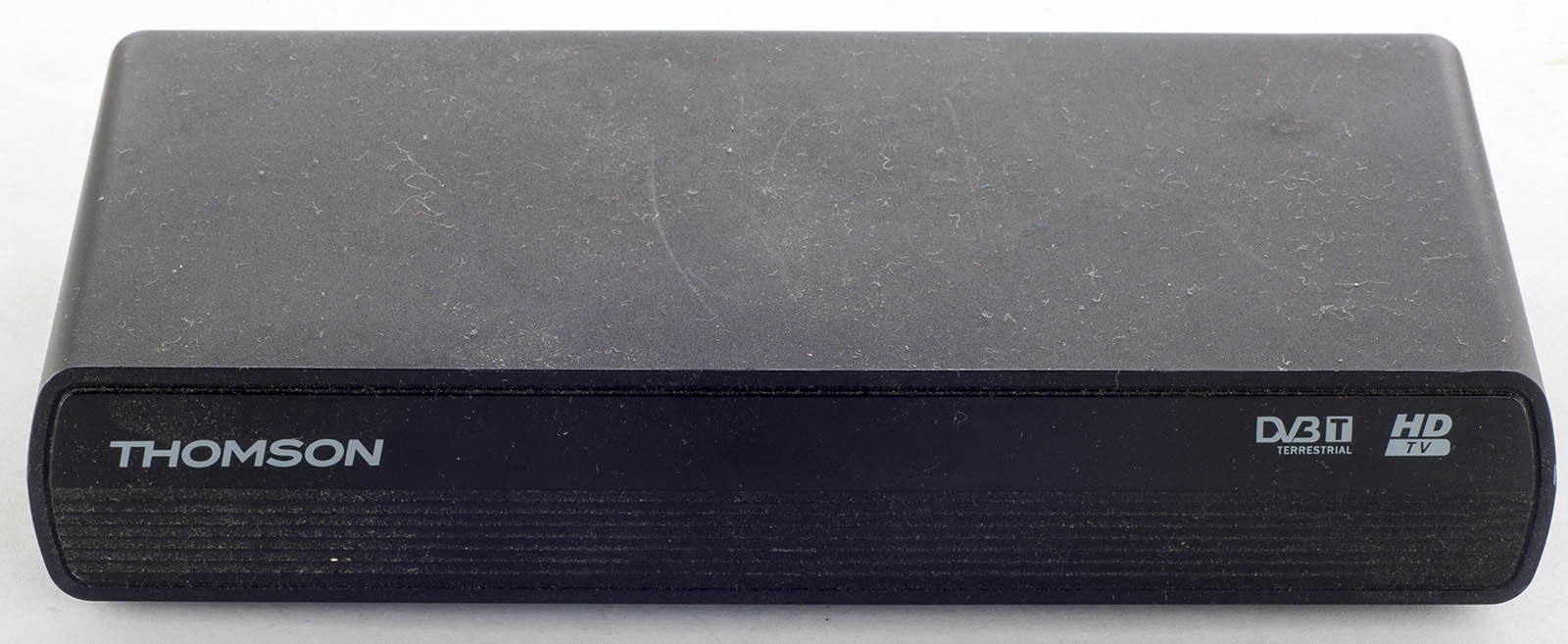
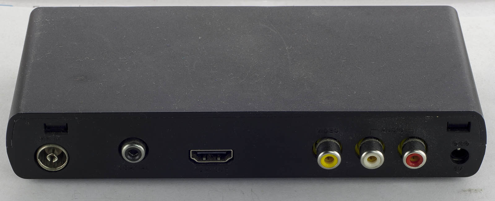
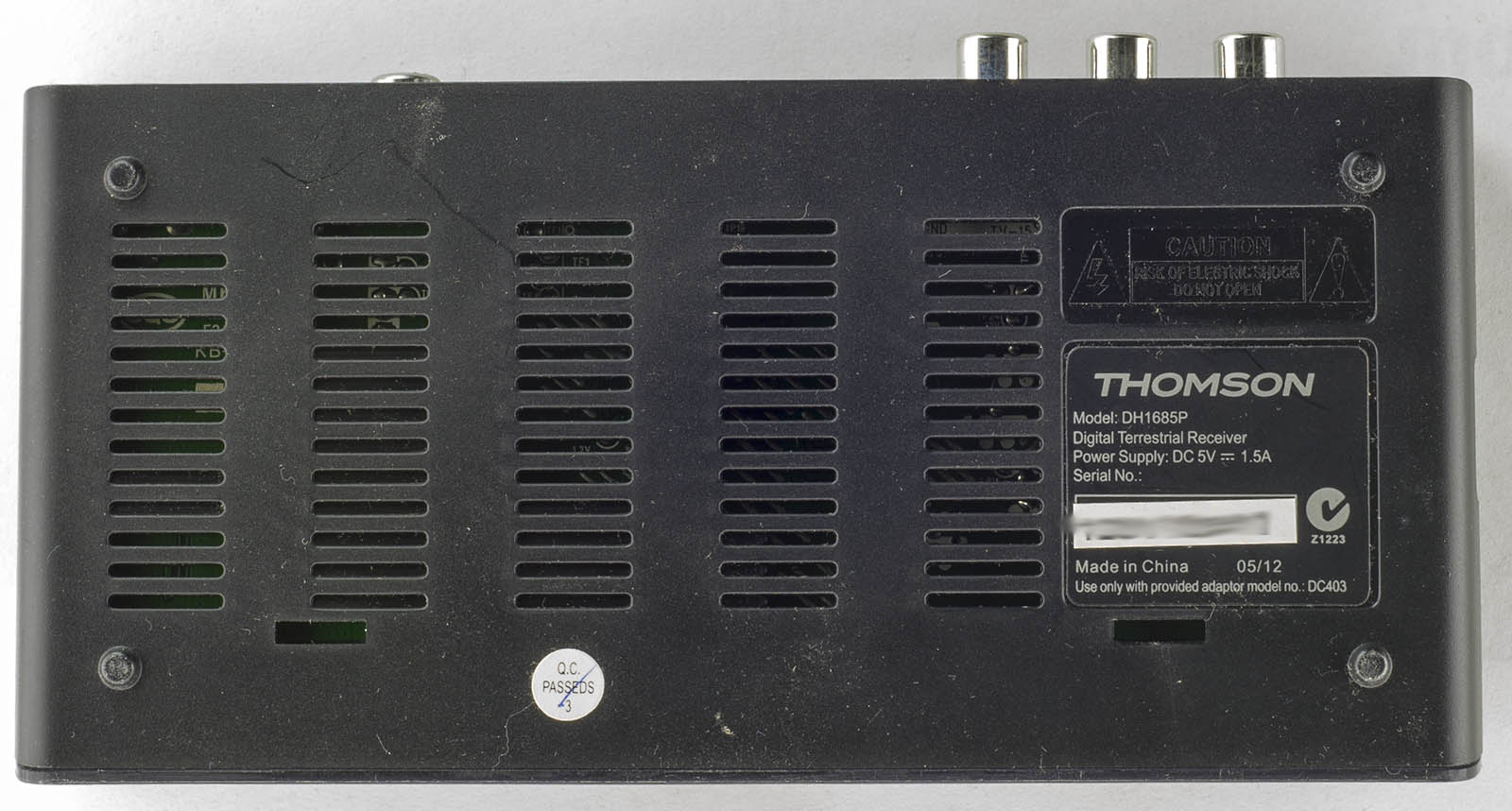
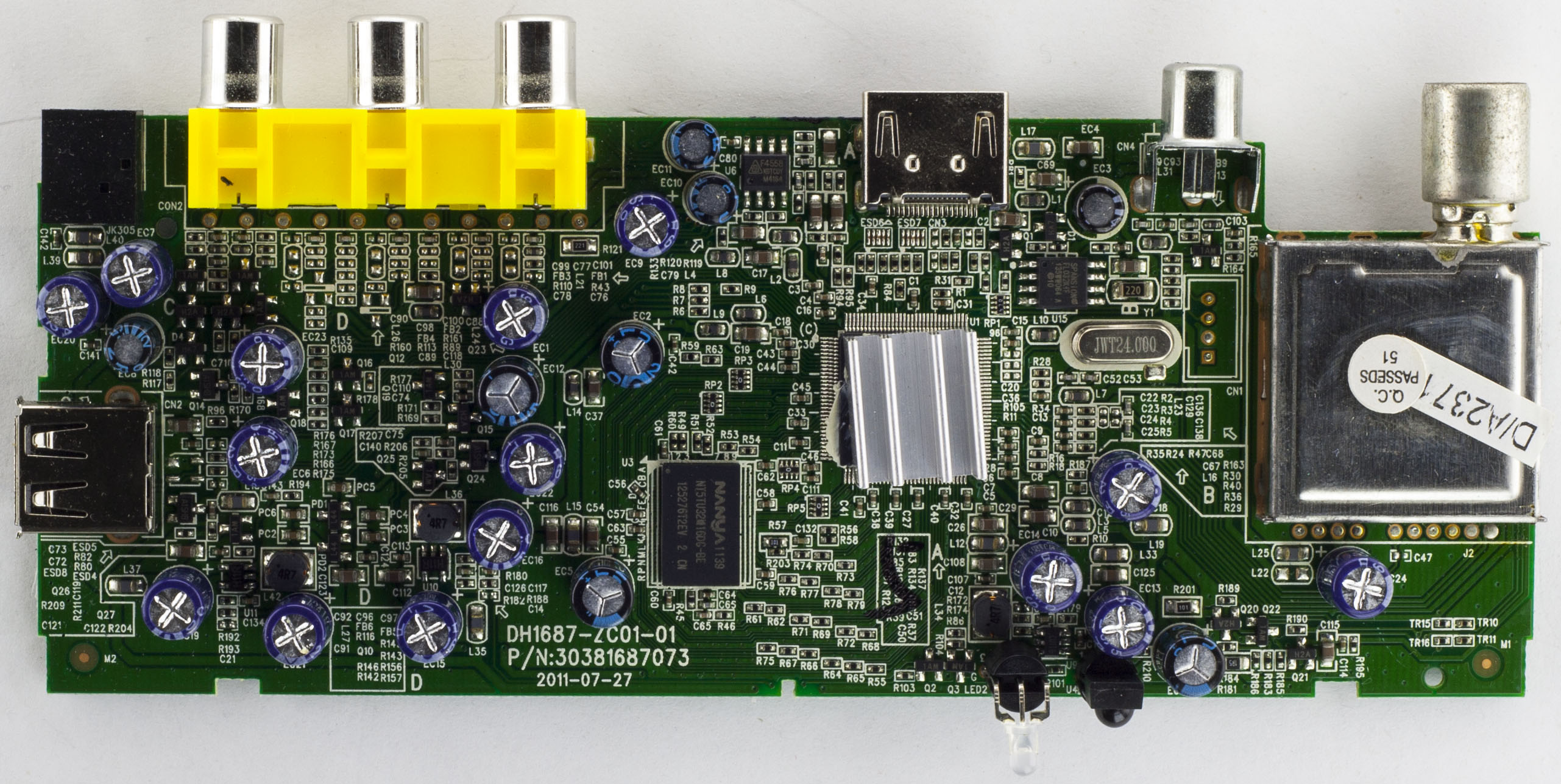
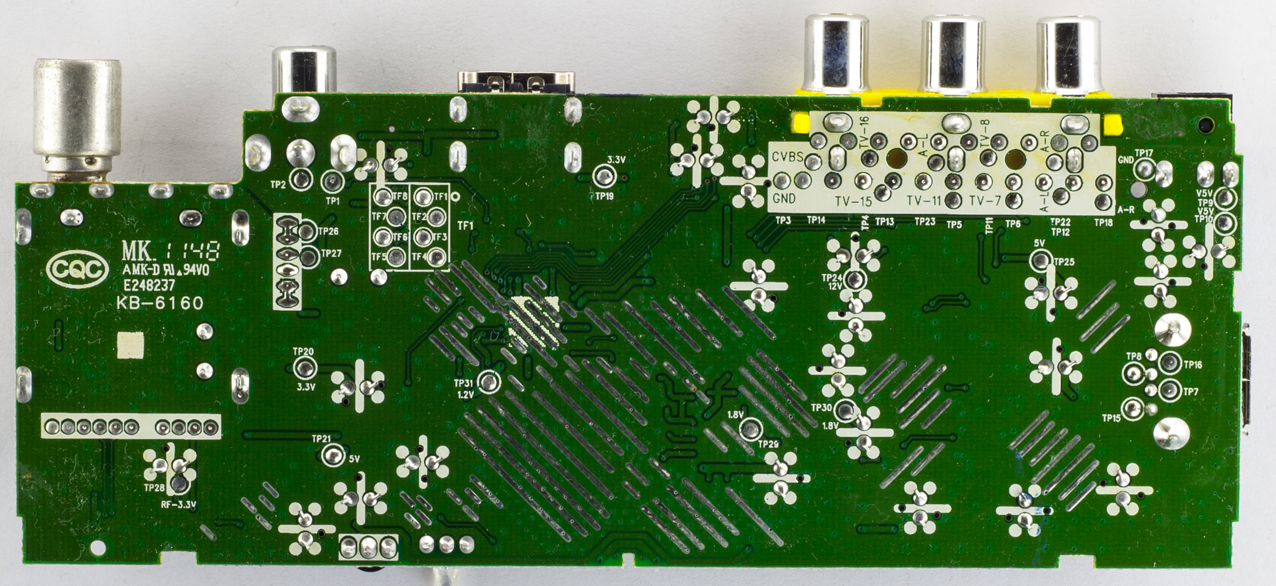
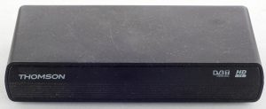
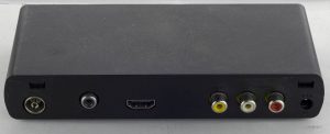
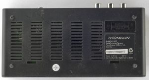
Today we’ll have a quick look at the Thomson DH1685P Digital Terrestrial Receiver which is a digital TV receiver that outputs to HDMI, composite, coaxial and has a USB input on the side.
A couple of clips later and we’re in.

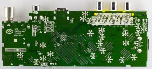
We have a single chip solution with a small heatsink, the RF side with shielding, a whole bunch of Acon 220uF capacitors all over the board and there are two 6 pin DC-DC converters (H11R). They have left some of the copper exposed on the bottom and tinned it for slightly better heat dissipation. PCB date code is 48th week of 2011.
(more…)
Read Full Post »
Posted in Teardowns on Sep 2nd, 2017
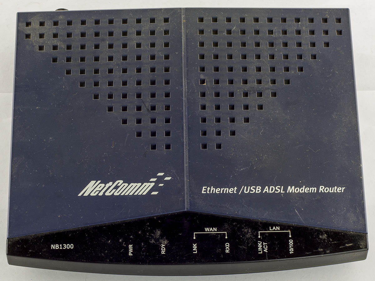
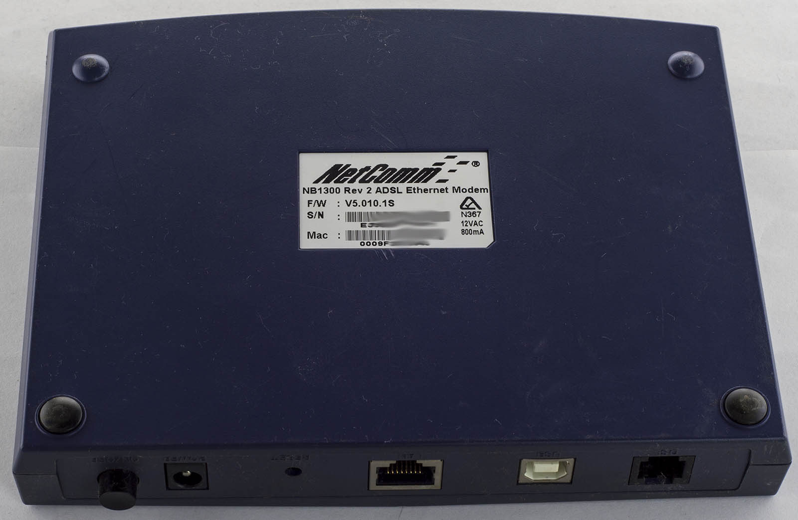
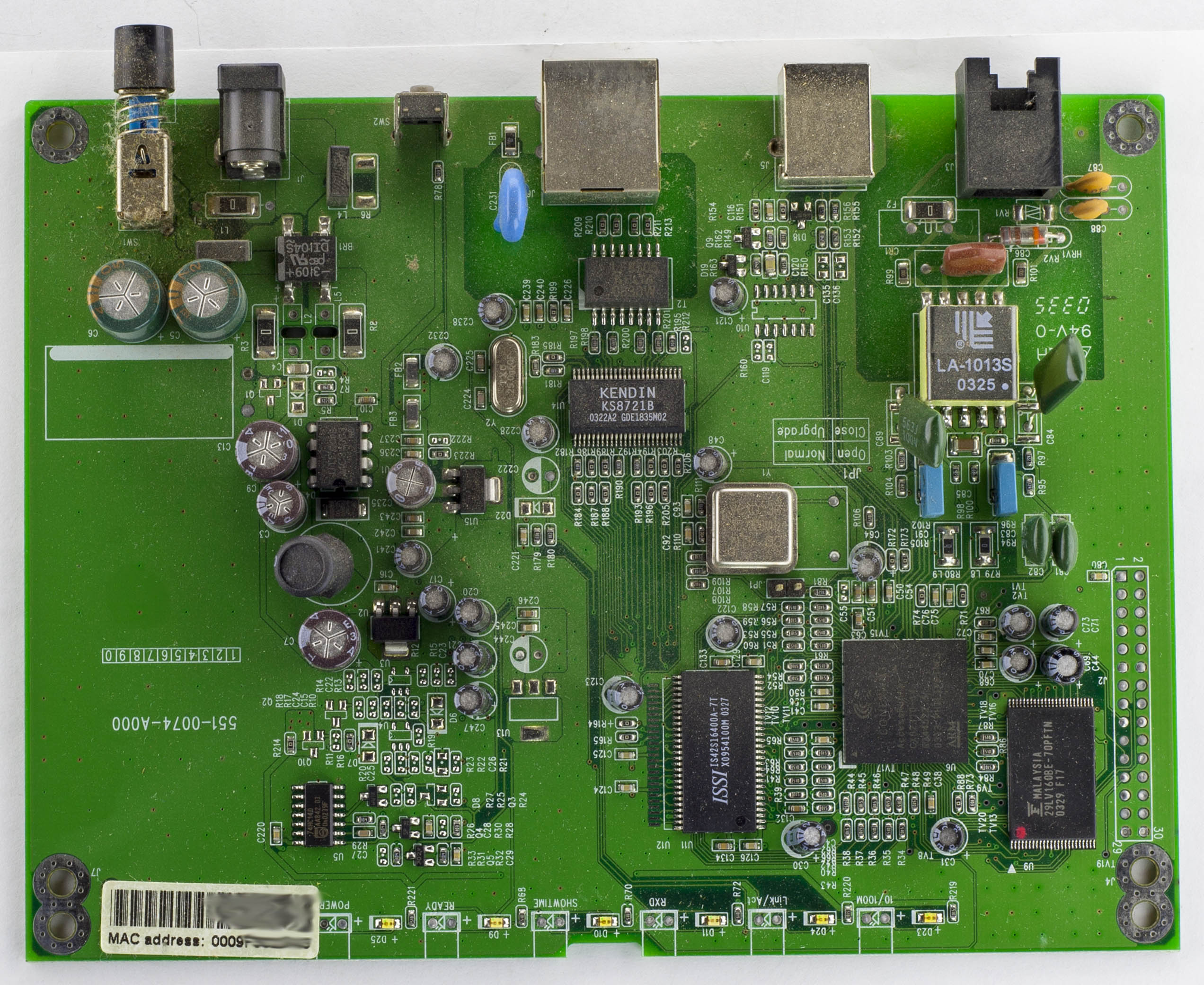
Today we’ll be taking a look at the Netcomm NB1300 Rev2 ADSL Ethernet Modem which is an 10/100 Ethernet & USB ADSL modem, quite an old one back from 2003 and a bit dusty too.
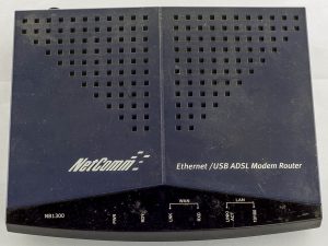
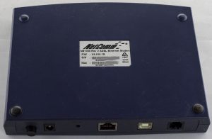
Two screws later and we’re in.
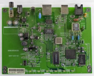
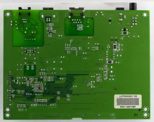
Looks like the layout is pretty relaxed, lots of space left over. We’ve got a fair few electrolytic capacitors which are all branded Teapo, we have a single chip solution and interestingly there’s a VCXO. Date code is 35th week of 2003.
(more…)
Read Full Post »
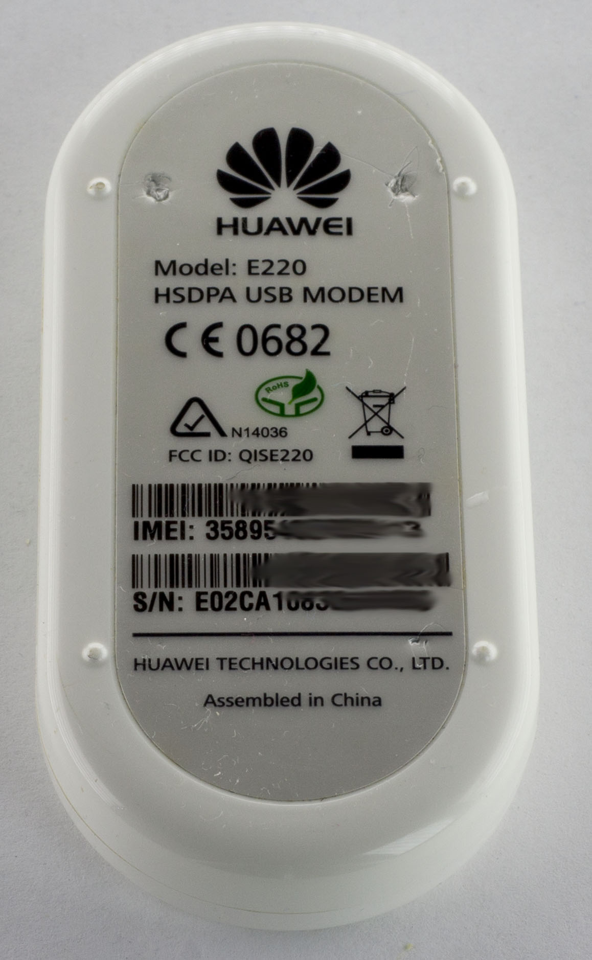
Posted in Teardowns on Jul 28th, 2017
A quick one today, we’ll be looking at the Huawei E220 HSDPA USB Modem which is a USB modem, kind of similar to the Telstra one shown a few weeks ago except it only supports 3G (and not NextG) networks with no external antenna support.

A few plastic clips and 1 screw later and we’re in.

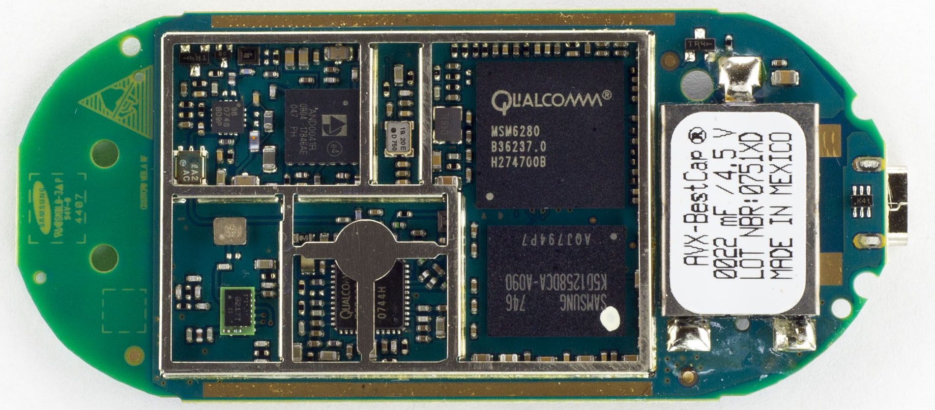
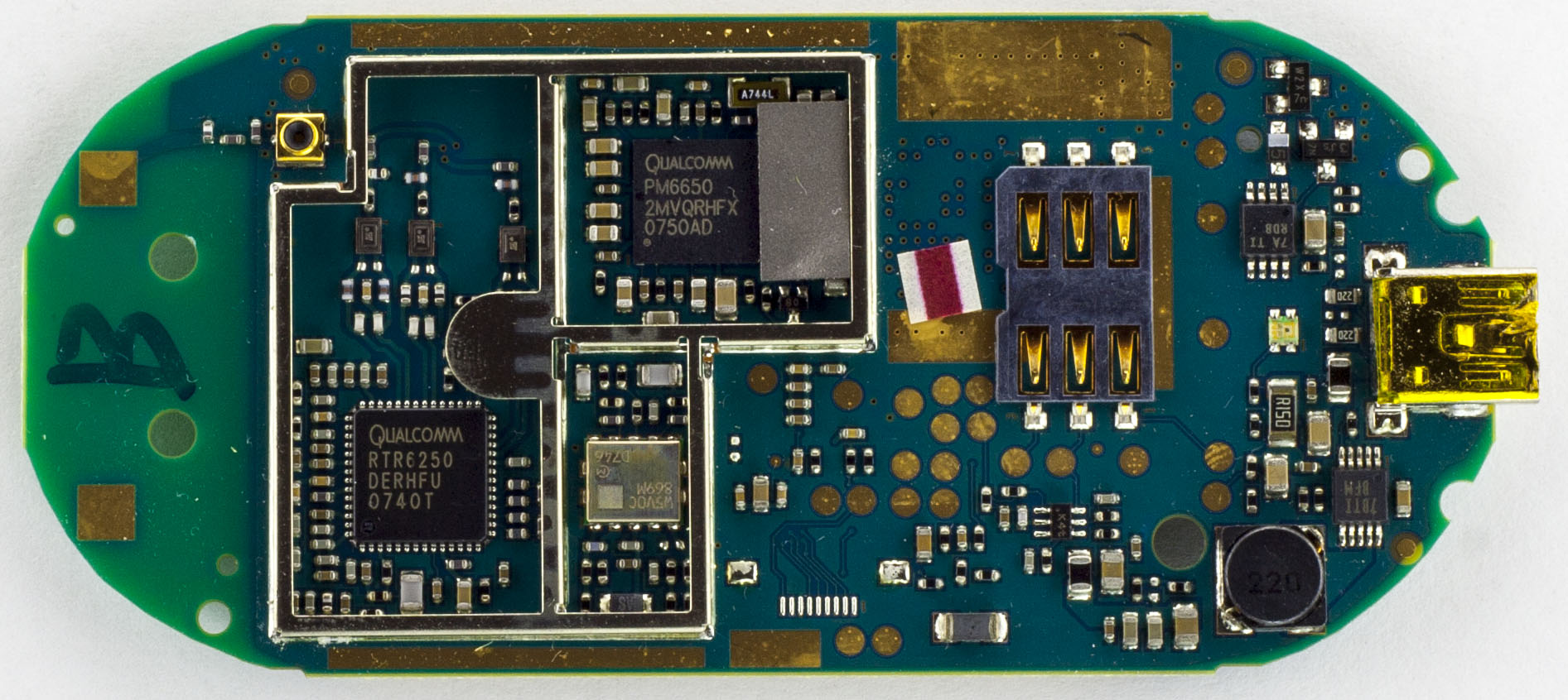
This time we did have some RF shields around all of the important chips. We seem to have a large 22mF (22000uF) 4.5V supercapacitor, I think this one is the largest I’ve seen on any PCB, this board must have some serious current spikes. There’s a Samsung logo on the PCB so I’m guessing they designed this board. There are a few little RF chips about.
(more…)
Read Full Post »
Posted in Teardowns on Jun 17th, 2017
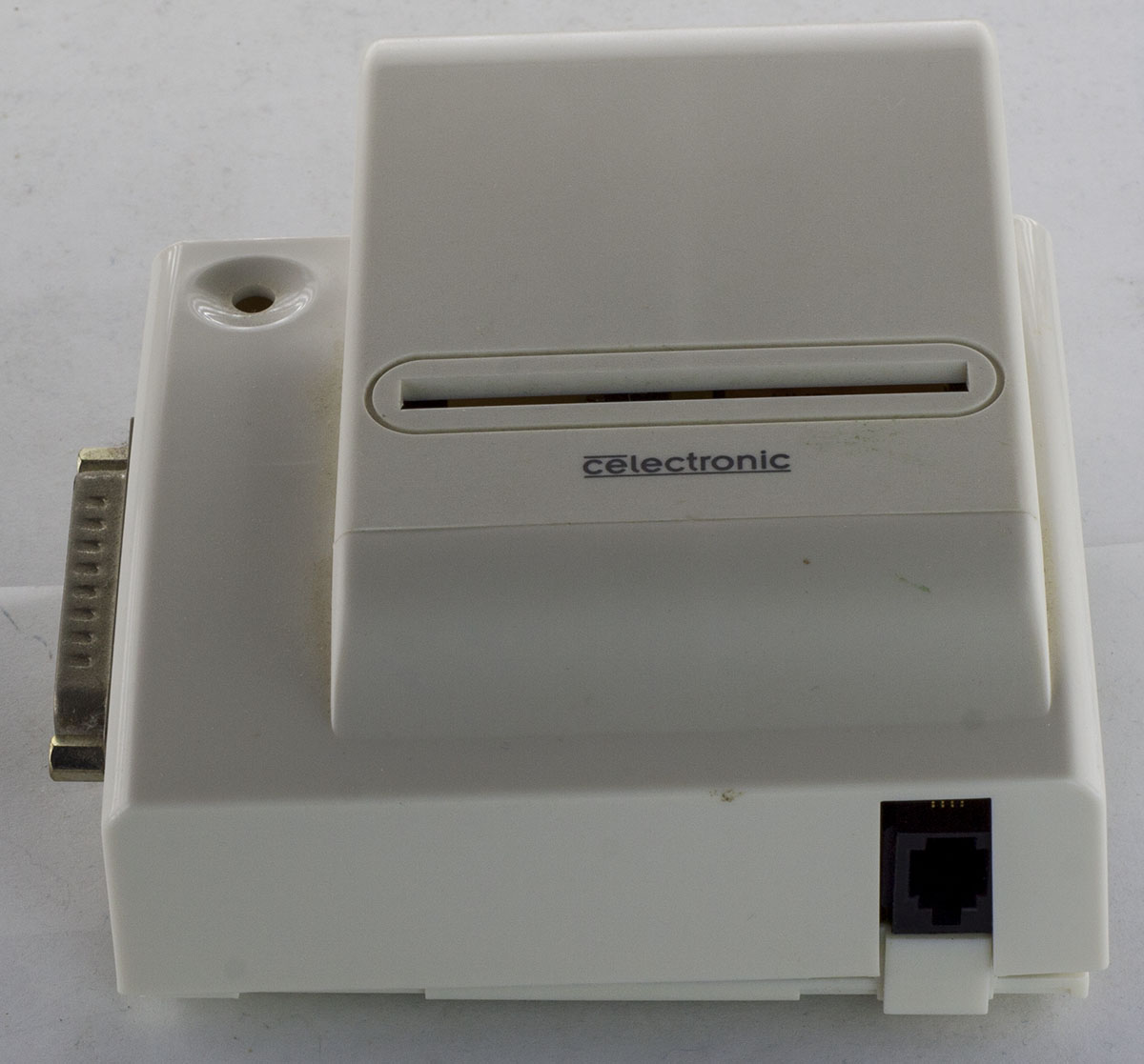
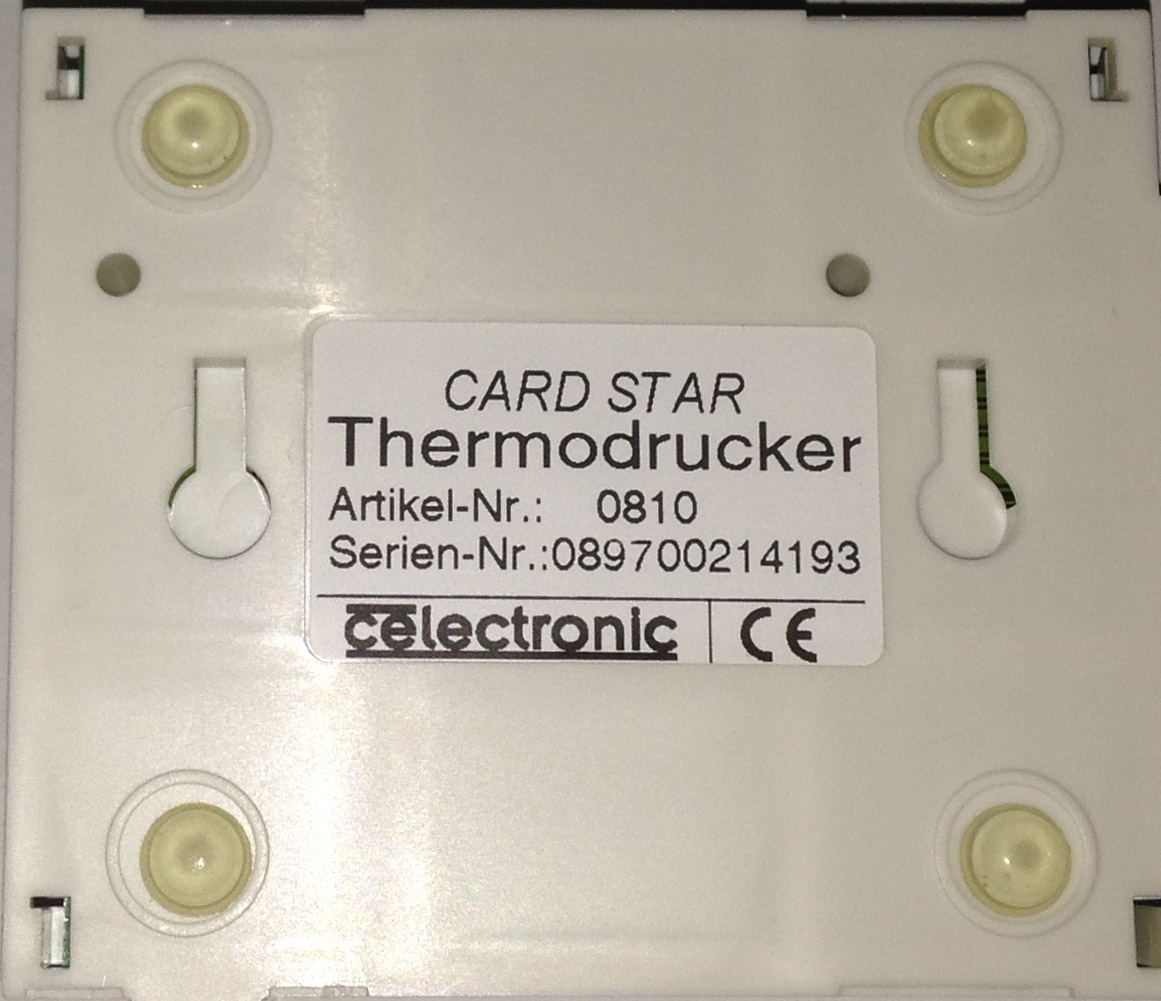
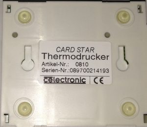
Just a quick one today, we’ll be looking at the Card Star Thermodrucker thermal printer, a low cost parallel thermal printer, I wonder how old the design is as it has a parallel port. I picked it up on Ebay about 2 years ago now to use for address labels when mailing out items. There seems to be low cost USB thermal printers for not that much more.

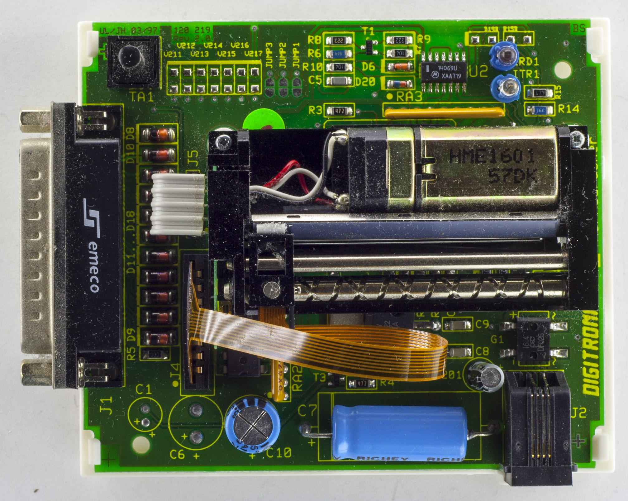
With the printer I got a parallel to USB cable and an overseas AC adapter rated for 9V AC at 300mA, I’ve been wanting to change the adapter for something else, so we’ll have a quick look at doing that too.

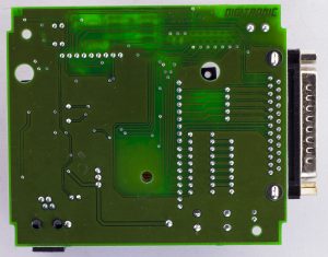
A few clips later and we’re in. We can see the thermal print head and motor sit above the PCB, held in place by 2 screws/risers, the print head connects via a flat flex cable and the motor just through some wires. There are some decent sized capacitors, Richey 1000uF 25V and Richon 1000uF 6.3V and we have zener diodes on some of the parallel port data lines. The PCB date code is 03/97!
(more…)
Read Full Post »
Posted in Teardowns on May 7th, 2017
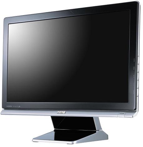
Today we’ll be looking at the BenQ 21.5″ E2200HD LCD Monitor which features a 1080p display, HDMI / DVI / VGA inputs, speakers and a headphone jack. This one stopped working one day, I’ve had it for 8 years so decided to take it apart to see what was wrong.
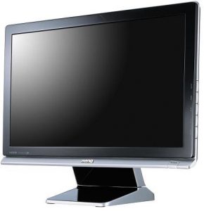
(forgot to take some pictures of it before I took it apart, so here’s a stock image)
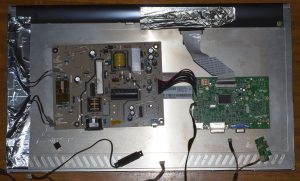
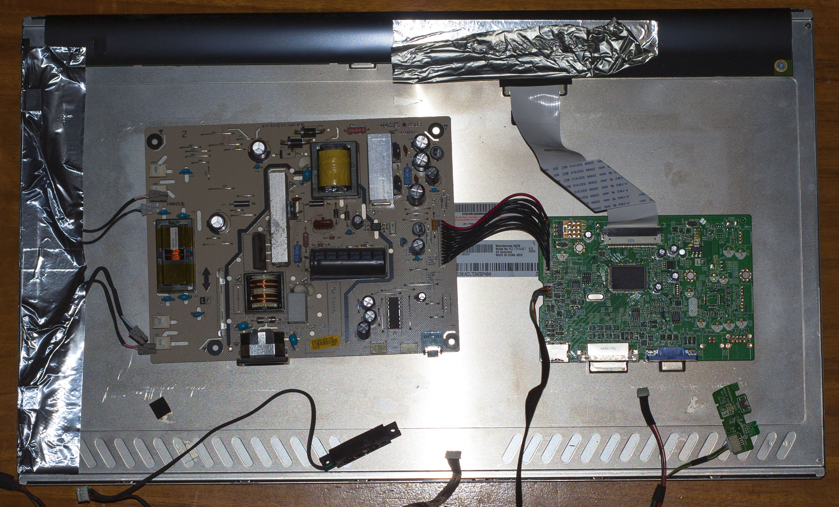
After a couple of tough clips and removal of the stand, we’re in. There was a metal cage holding the power and logic boards but it was just stuck on with some shielded tape, no screws whatsoever which was odd. Powering it up by the power button, I can see the power LED turn on for a fraction of a second, does this 2-3 times before it no longer lights the LED.
(more…)
Read Full Post »
Posted in Teardowns on Apr 7th, 2017
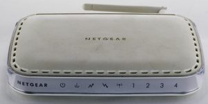
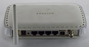
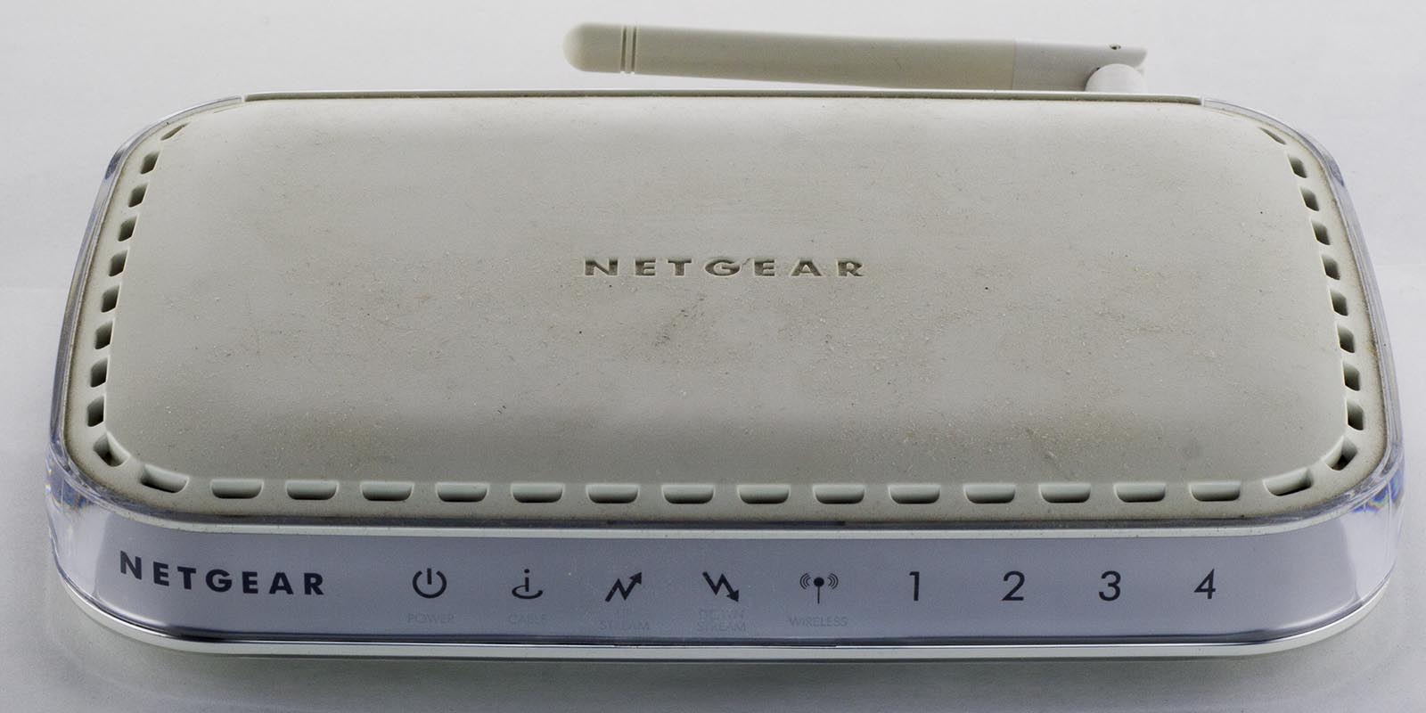
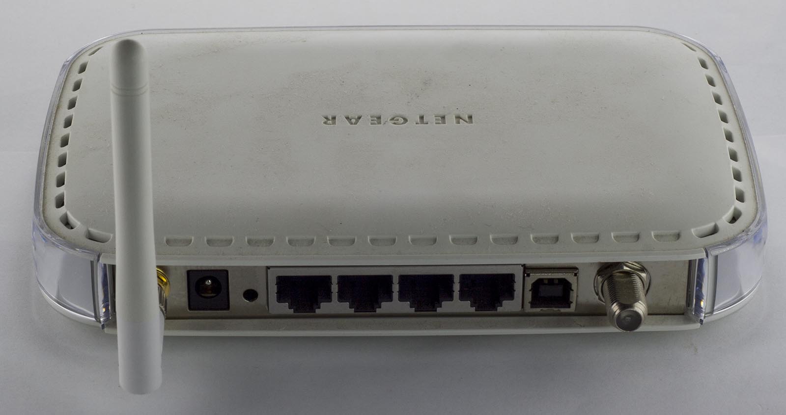
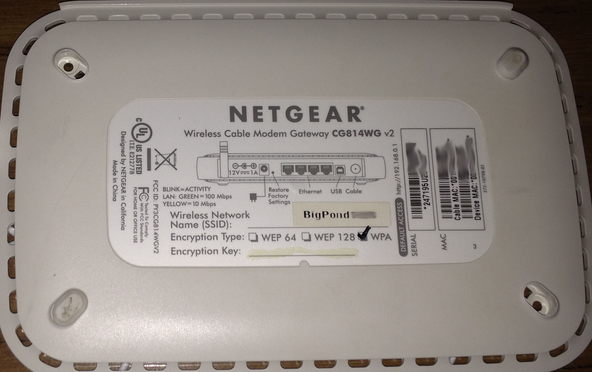
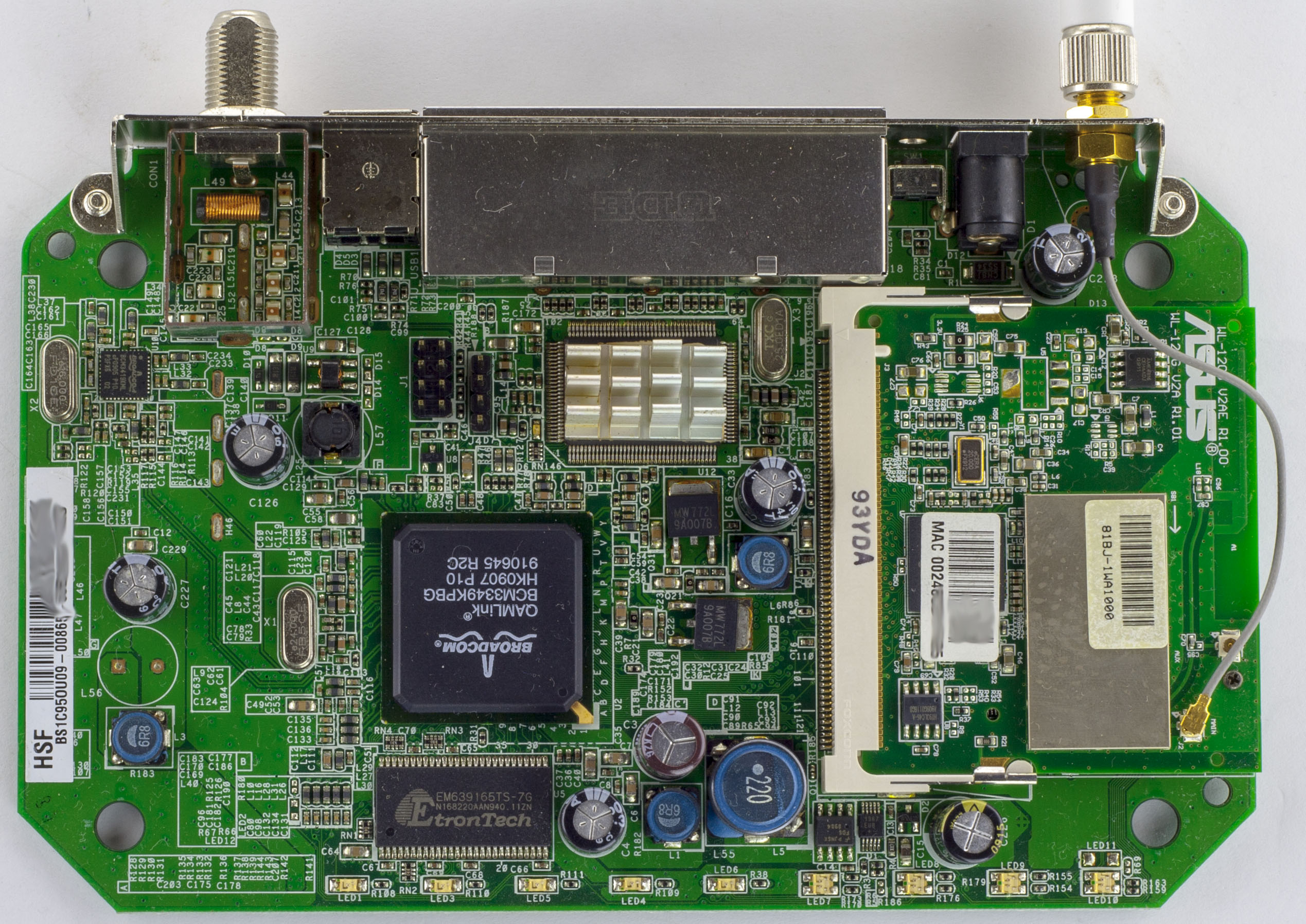
Today we’ll be looking at the Netgear Wireless Cable Modem Gateway CG814WG v2 which is a cable modem/router with 4x 10/100 network ports, 1 USB port and 802.11b/g Wifi.
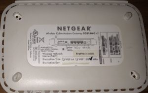
Four screws later and we’re in
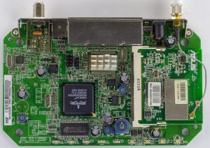
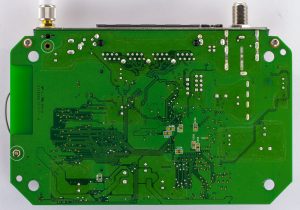
We’ve got a 2 chip solution with only a heatsink needed for the Ethernet chip and the usual Mini PCI wifi card (which seems to be common for devices of this time). Only 1 DC-DC converter on board with a large 22uH inductor plus there are some noticeable 6.8uH inductors sprinkled around too, the caps are branded OST / TEAPO. We also have some 4×2 pin and 4 pin male header near the main chip. The PCB date code is 14th week, 2009.
(more…)
Read Full Post »
Posted in Teardowns on Feb 19th, 2017
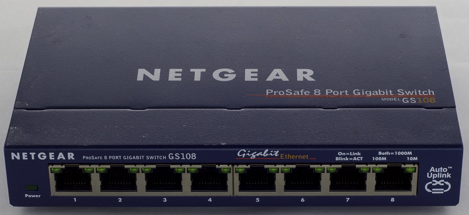
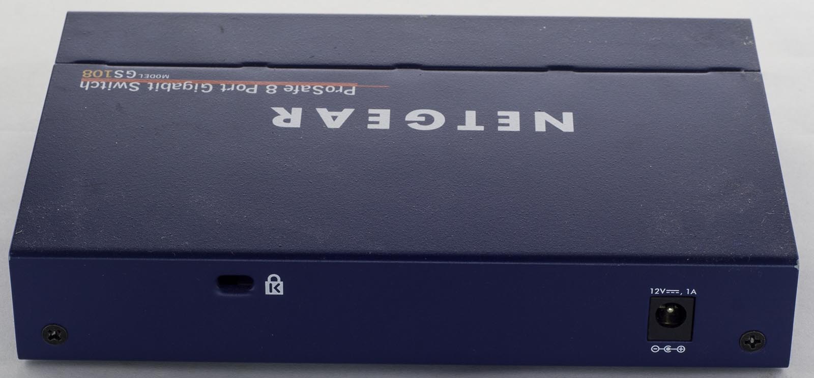
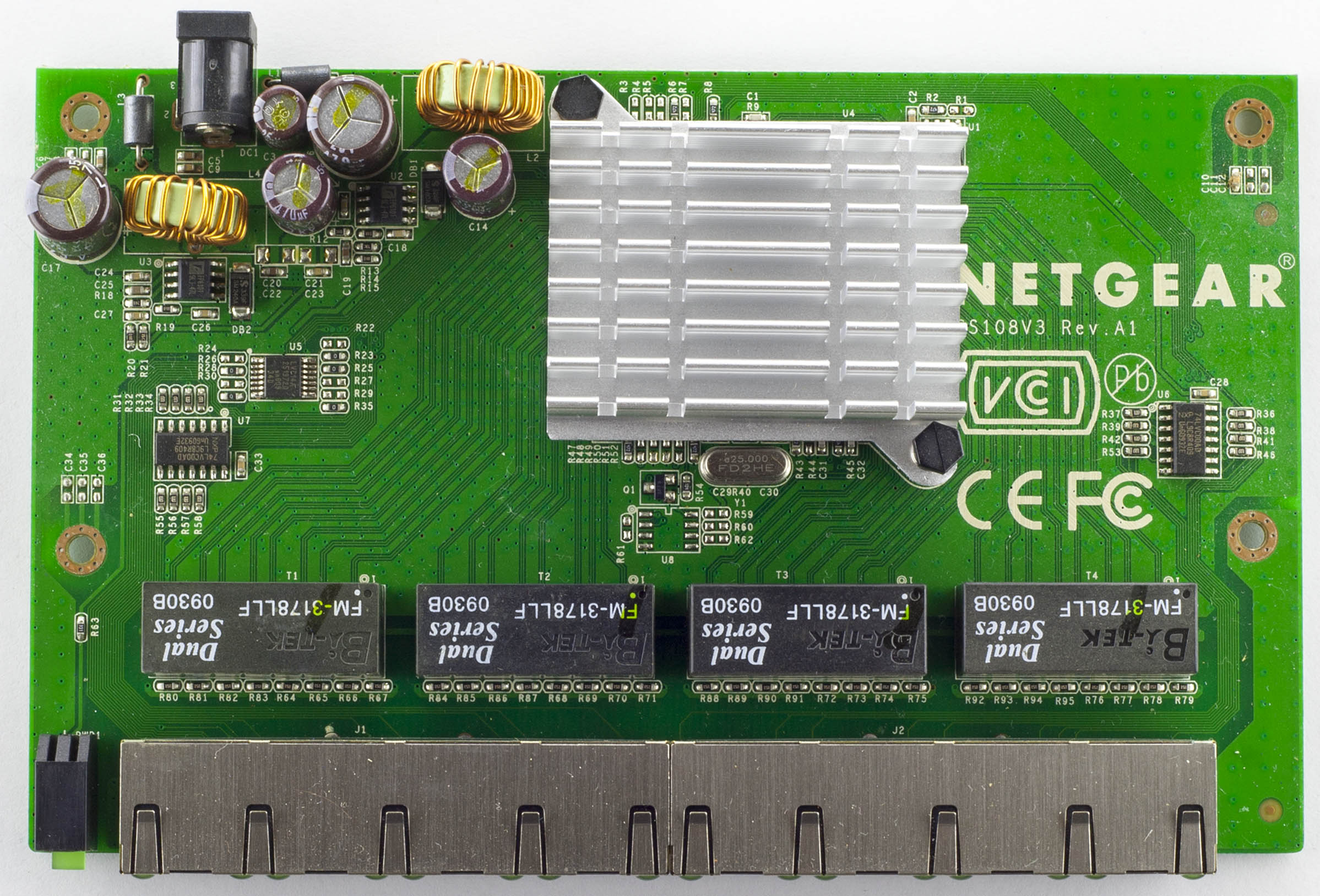
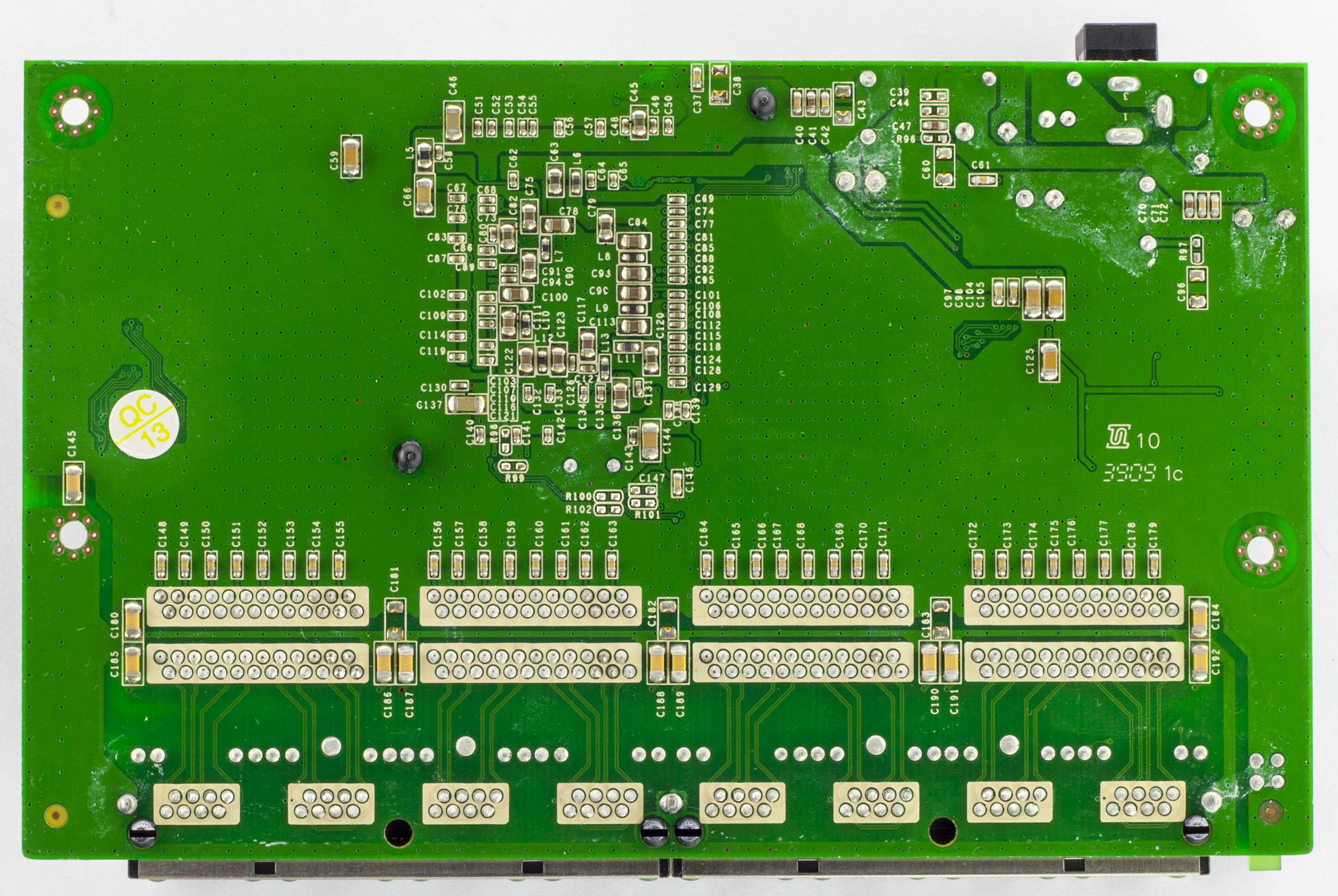
Another quick one, today we’ll be looking at the Netgear ProSafe GS108 8 Port Gigabit Switch which is an unmanaged 8 port gigabit switch and has a little Kensington lock on the back.
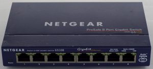
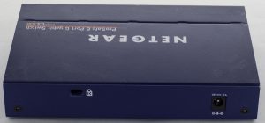
Two screws later and we’re in.


There are a couple of logic chips hanging around which isn’t too common on low port switches, a pretty decent heatsink on the main chip and a good amount of via stitching. PCB date code is 39th week, 2009.
(more…)
Read Full Post »
Posted in Teardowns on Jan 14th, 2017
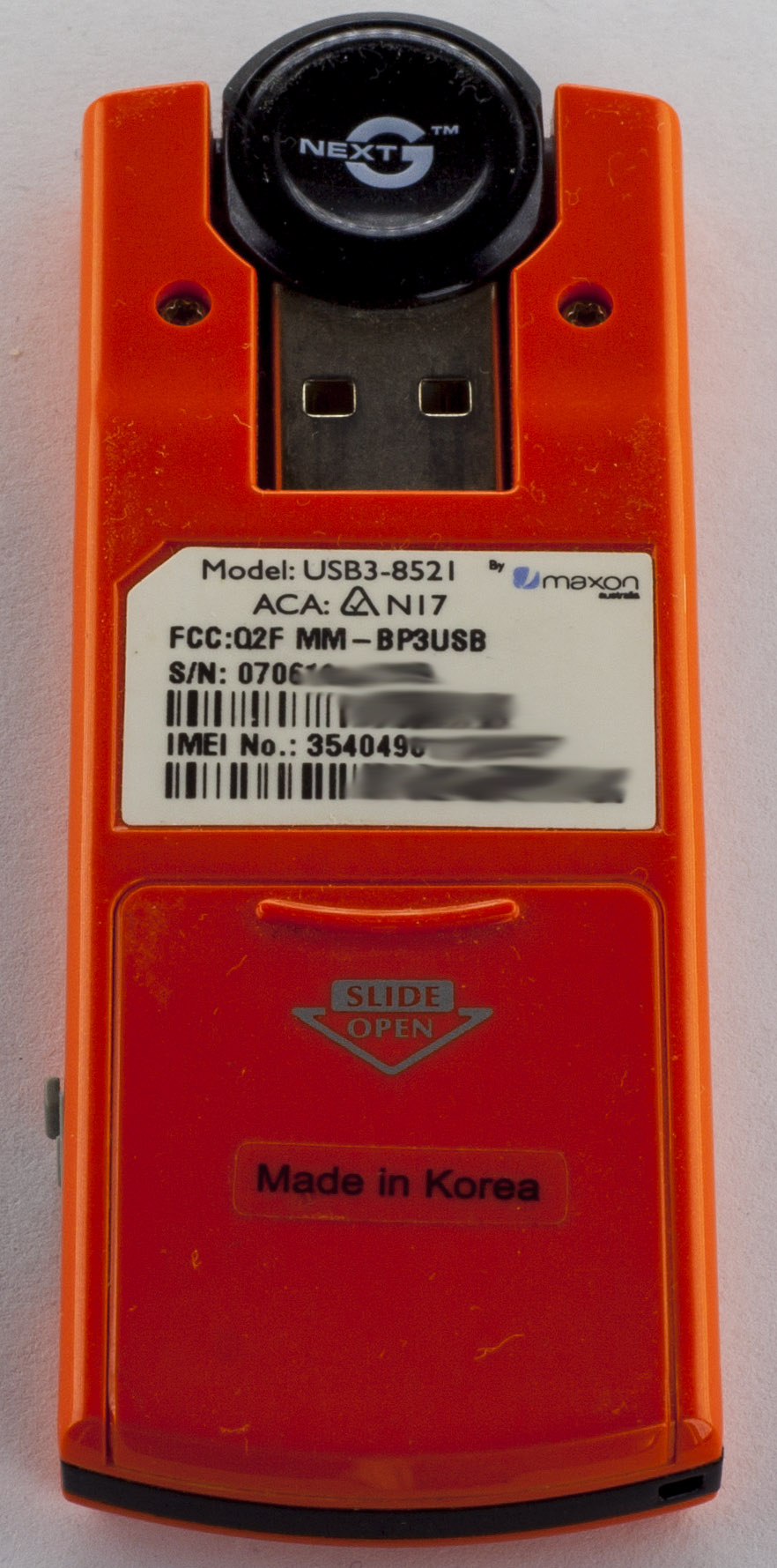
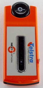
A quick one today, we’ll be looking at the Telstra NextG Turbo USB Modem (USB3-8521) which is a USB modem using the NextG network to have Internet on the go. It has a slide where the SIM card goes and you can connect an external antenna.

Four screws later and we’re in.
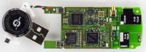
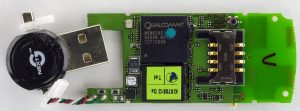
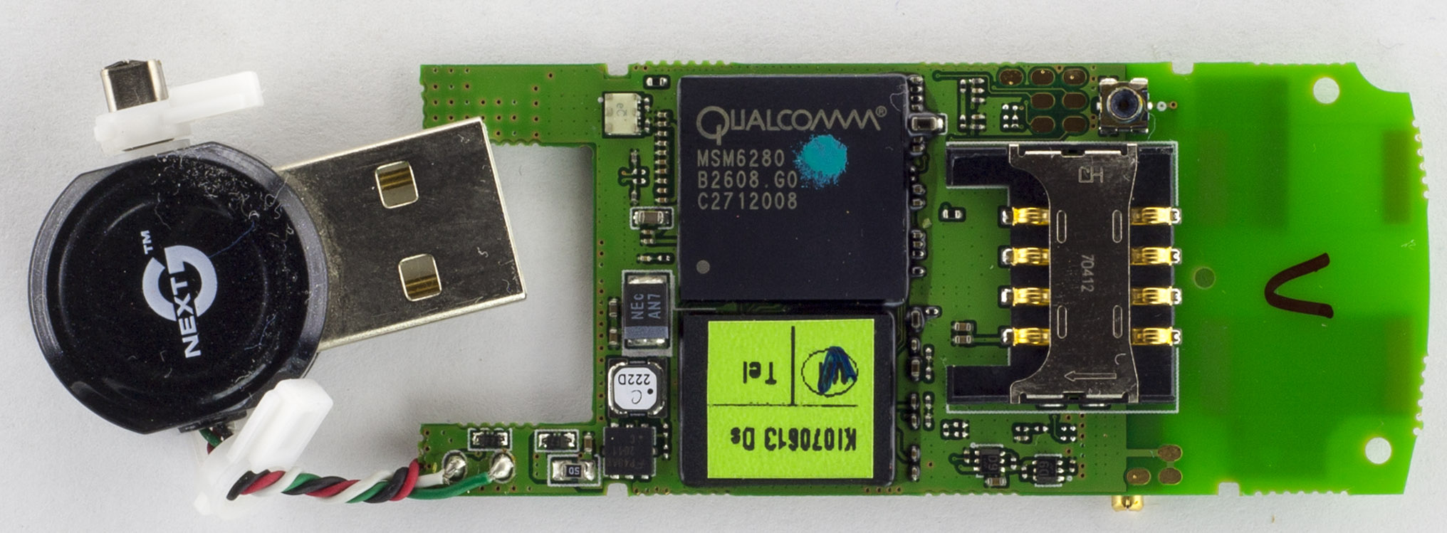
The USB connector is just attached via the 4 twisted wires which seems like it would hold up to some movement. We have 2 different Mobinus branded PCB antennas, the 2 white RF output transistors nearby and there is an external antenna connector on the bottom for the other antenna. There is a guard trace around all the RTR and RFR chips but no need for a RF can it seems. This board is a complete Qualcomm solution board (apart from the memory).

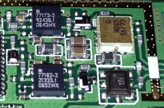
There are two small chips next to the RTR chip, then there are 2 small SOT23 (or smaller) 4 pin looking devices, then a ceramic package which is likely to be gold plated and another custom package next to it.
(more…)
Read Full Post »
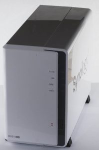
Posted in Teardowns on Dec 18th, 2016
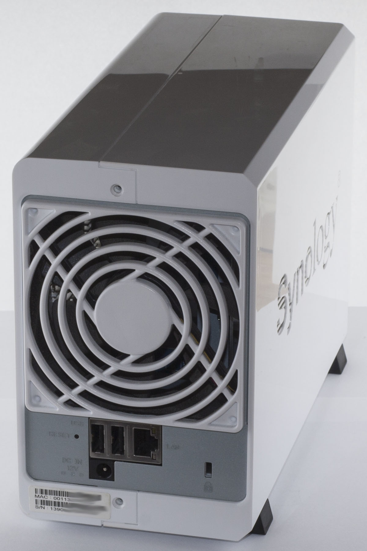
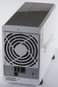
Today we’ll be looking at the Synology DS214se Dual Bay NAS (Network Attached Storage) which is similar to the single bay DS112J NAS except that this one has 2 hard drives to allow for RAID1/0, it has the standard Gigabit Ethernet and 2x USB 2.0 ports.
Two screws later and we’re in.

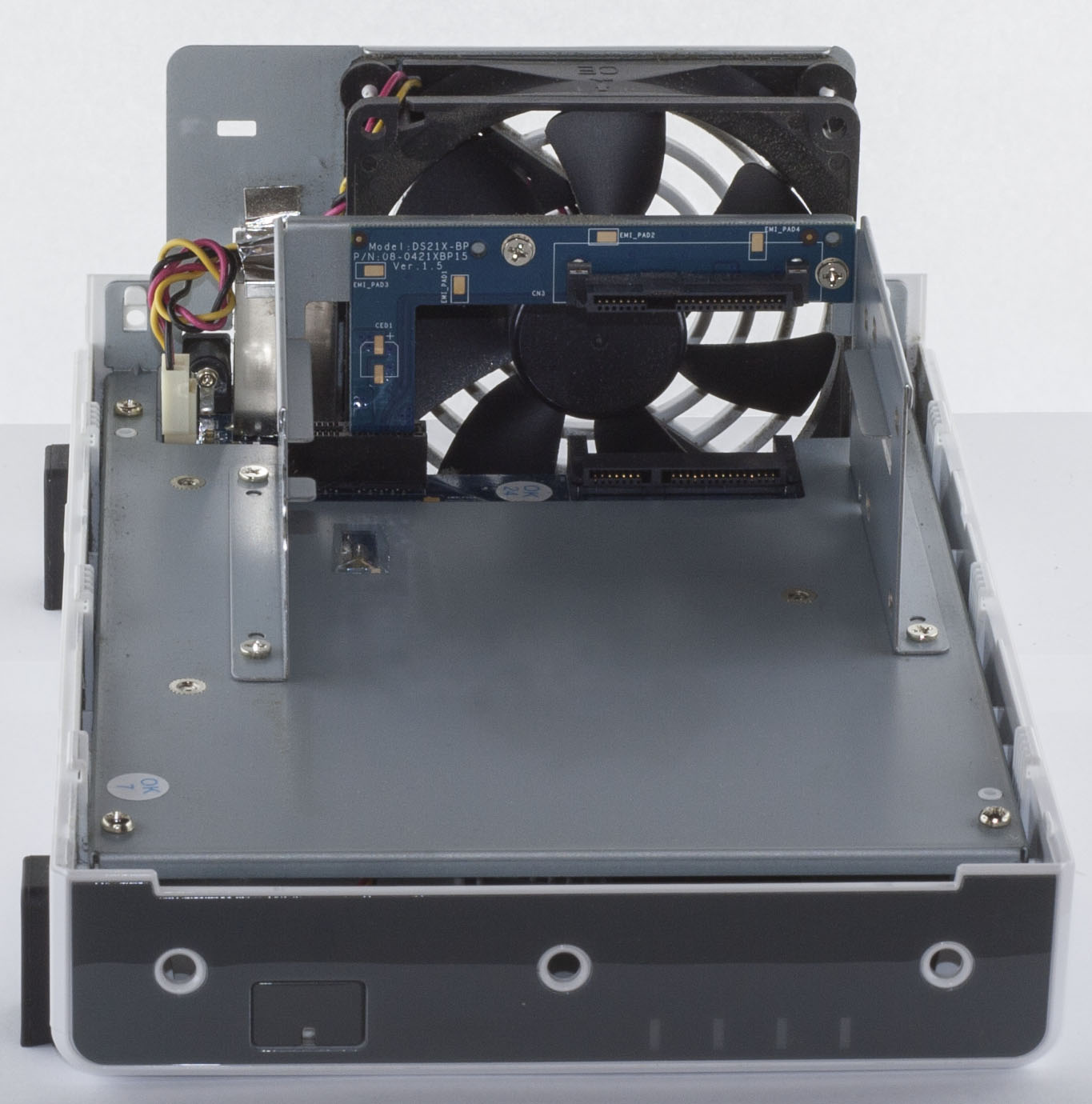
Once inside, we can see there is a backplane PCB for the second hard drive, they are only using the right slot of a PCI-Express x1 connector.

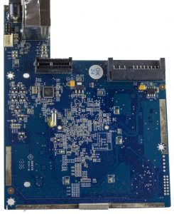
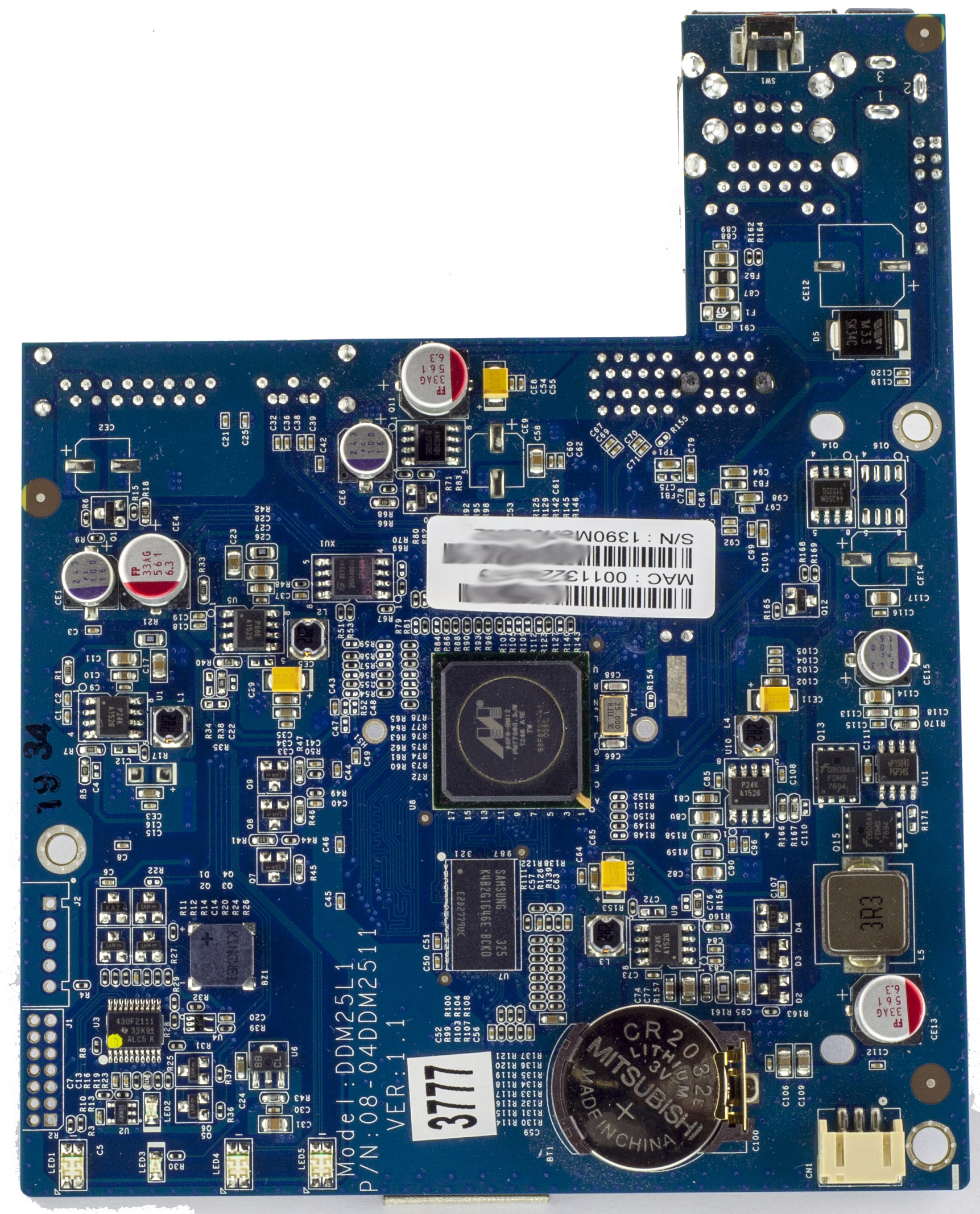
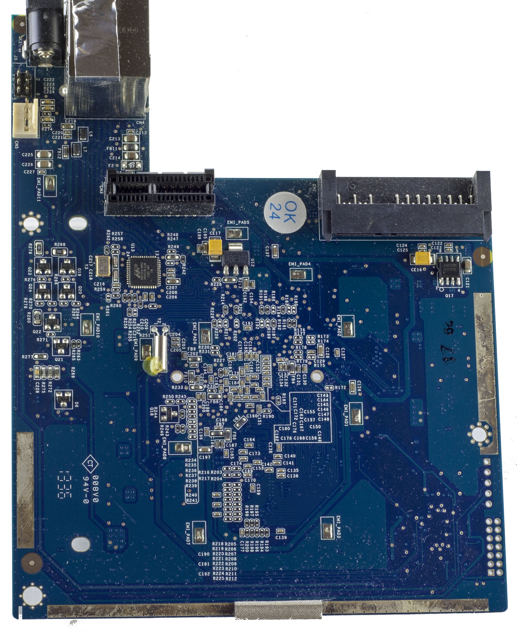
As per the single bay, we’ve got lots of EMI pads (but missing the pads/pins) and some on the PCB edges too. There are 2 unpopulated connectors on the bottom left of the PCB, a 6 pin connector near the power input jack and they have an SMD buzzer on the PCB. PCB date code is 36th week of 2013.
(more…)
Read Full Post »