Feed on
Posts
Comments

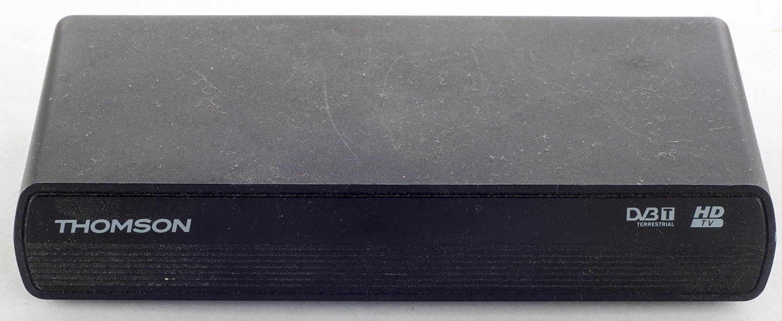
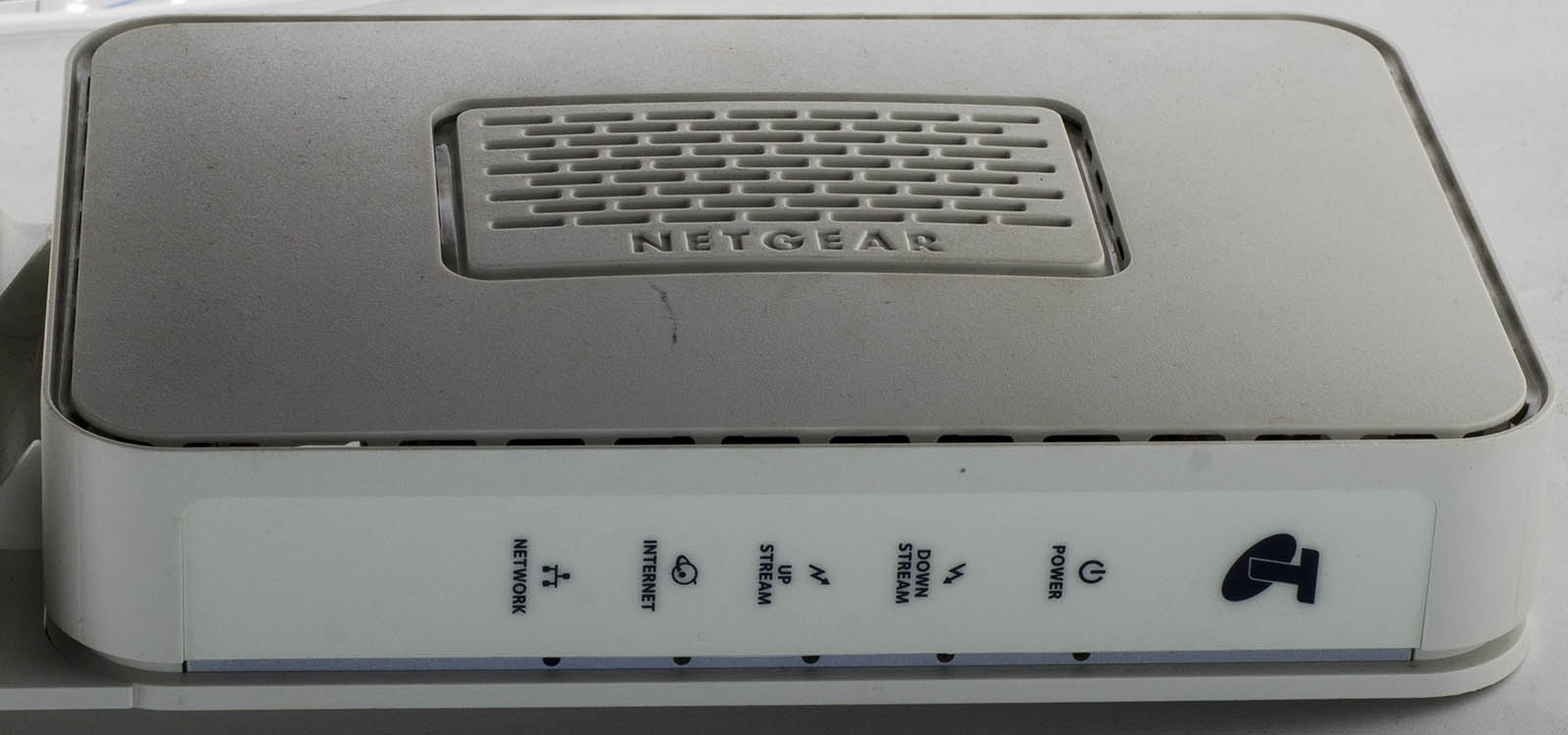
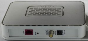
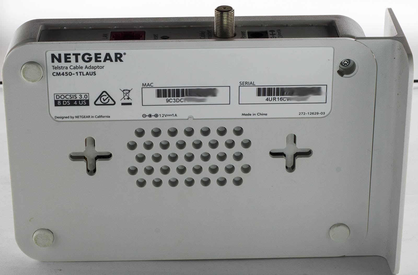
Today we’ll be taking a look at something a little bit modern, the Netgear Telstra Cable Adapter (CM450-1TLAUS) which is a cable modem with just the one Gigabit Ethernet port and RF connector.

4 screws later and we’re in.

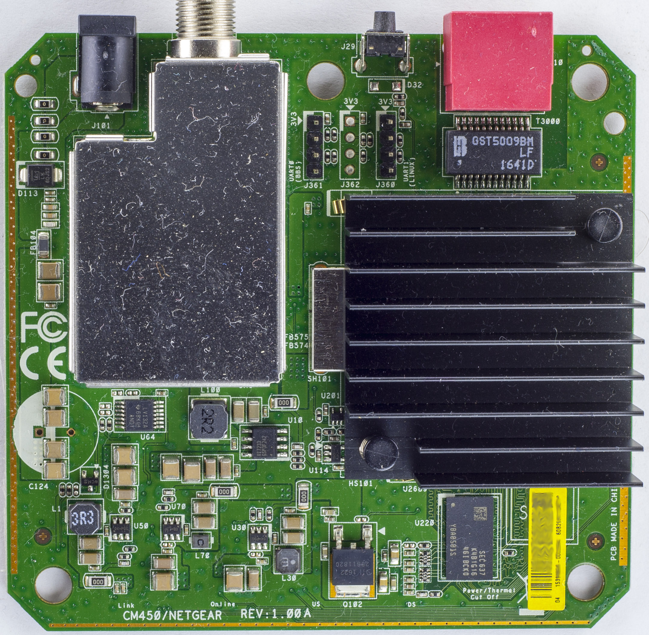
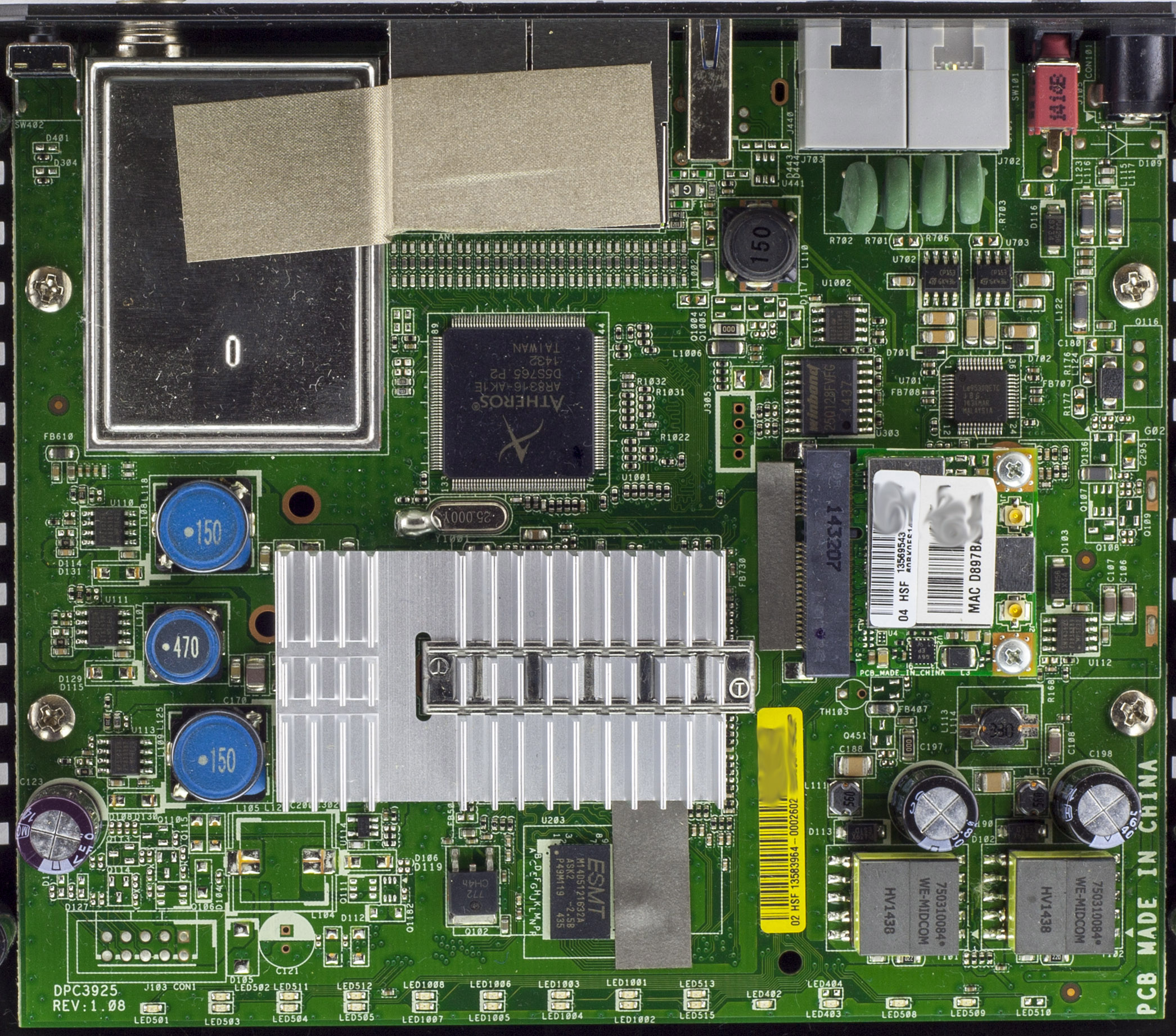
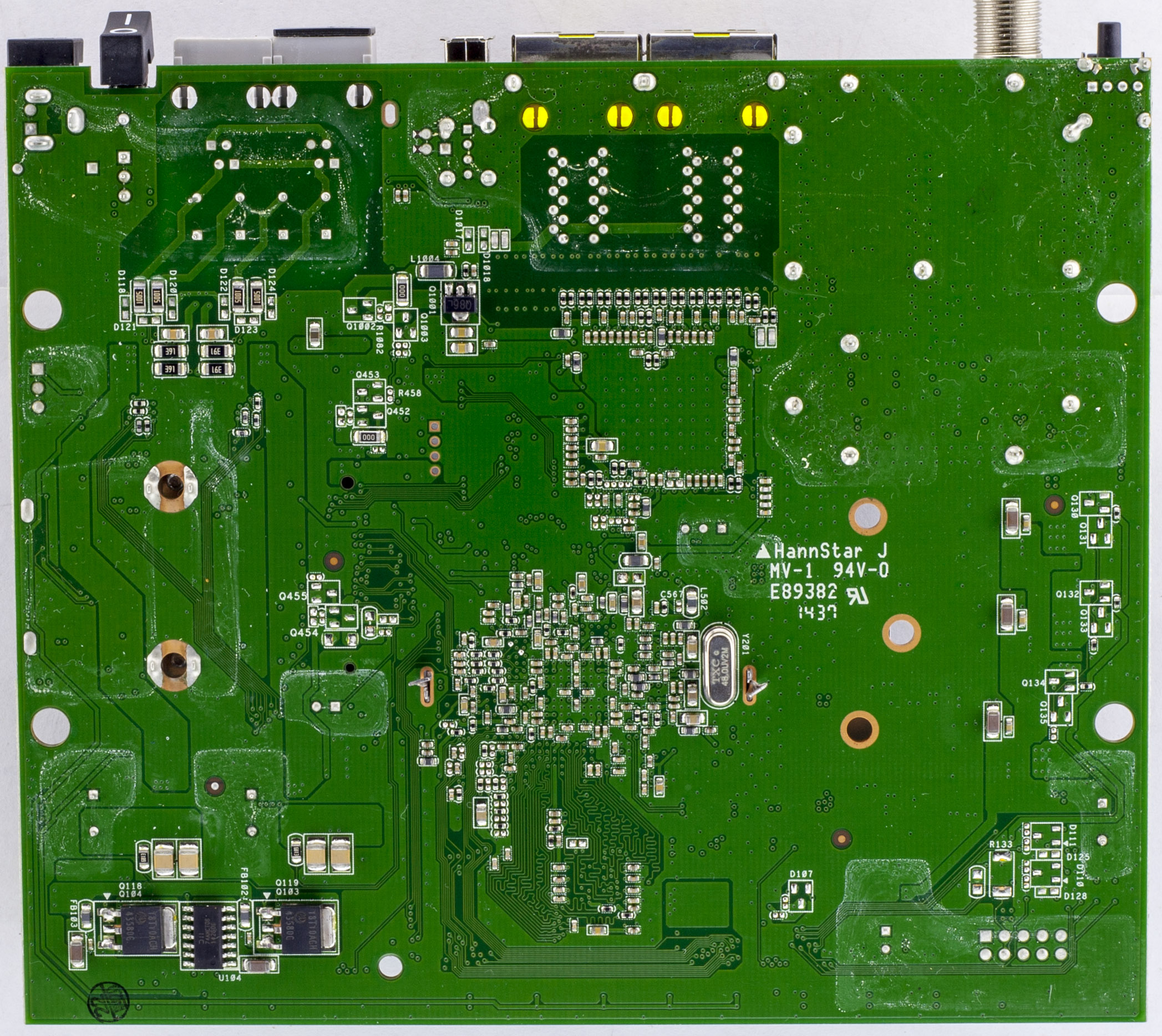
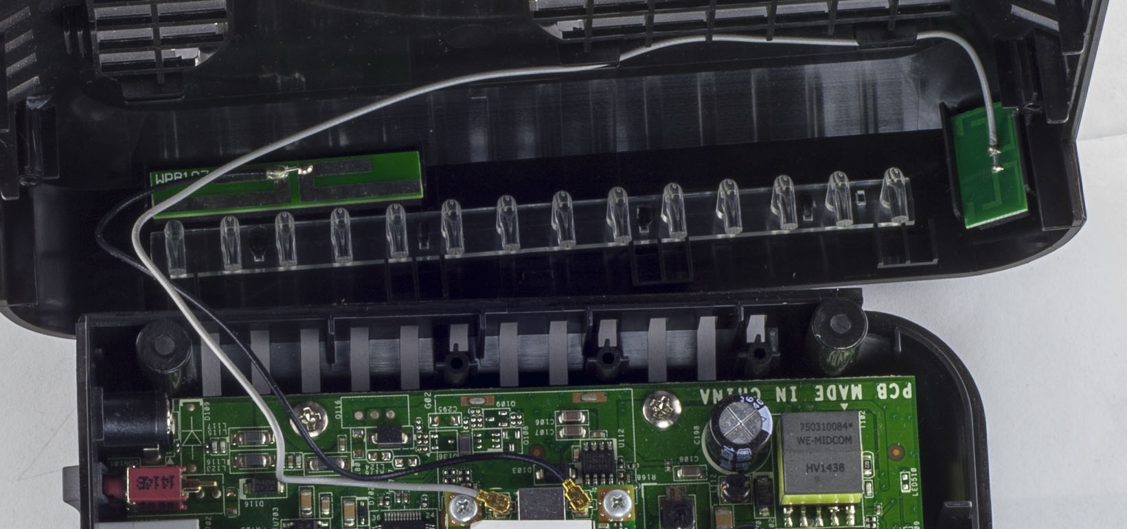
We have a single chip solution with a large heatsink and the RF side has the usual RF shield. They have exposed ground strips on 3 out of the 4 sides of the board and there are no electrolytic caps to be found, they even had a footprint for one to the left but had the option of SMD caps too. Interestingly there are 2x 4 pin headers, labelly nicely, one reads UART0 (BBS) and the other UART1 (LINUX).

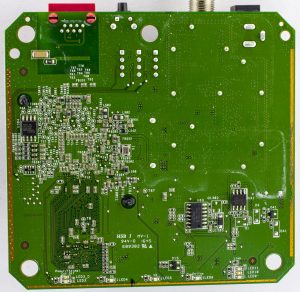
We have some logic chips around, an LV132 Quad NAND gate and on the bottom an 74HC74D Dual D-Type Flip-Flop and an LM358 too. PCB Datecode is 45th week of 2016.

For the power side, we have 4x DC-DC converters with inductors ranging from small to large, the largest one is the Richtek RT7233 18V 4A while the others are 6 pin chips (2x 04-P0G, 1x C8-L2P) which I can only assume might also be Richtek chips as the DC-DC’s don’t use an external diode.

(more…)

Read Full Post »

When finding out that one cell of my 3x 4S 1300mAh batteries were discharged to 3.3-3.4V (other cells were 3.7-3.8V) after not flying for 2-3 months, I was a bit surprised, these batteries were one of my first batteries purchased about 1.2 years ago. I’ve tried to be better now, checking packs every month, I’ve got some old packs for the RC car that hardly get used so I wrote down the idea to do battery storage voltage monitoring a few months ago so let’s make it happen.

I’m thinking of using the nRF24L01 module (as it’s pretty low cost), using an ATtiny24/44/84 which should give us 6S support and have it powered from the first cell of the LiPo, it shouldn’t take too much current from the first cell as we stay in sleep/power down most of the time. Add in a few resistors, led, mosfets to turn on when we want to measure the voltage. I will coat the PCB in lacquer and cover it with heat shrink to protect against the environment and since the board needs to be as small as possible, I’m going to try the SMD version of the nRF24.

Check-in times for these sensors might be in the range of hours as battery voltage won’t change too much, it would be nice to have a graph over say 30 days but I might look into that later if I feel it’s worth doing, for the moment it will just show the sensor number, cells, status if it’s ok or not, battery cell voltages and last check in time. Server side would just be an ESP8266 with the nRF24L01 directly attached so no need for any other MCUs.

(more…)

Read Full Post »

Today we’ll be taking a look at the Cisco DPQ3925-X Cable Modem / Gateway which is a cable modem with 4x Gigabit Ethernet ports, 802.11n Wifi, USB port and 2 analog phone ports.

4 screws later and we’re in.

Looks like we have a 2 chip solution, one of them has a pretty large heatsink. There is a Mini-PCI Express Wifi adapter with dual antennas. There is an RF can for the cable input and some conductive tape connecting it to the ethernet ports which is a little odd as the ethernet shielding is grounded. We also have tape near the main processor going to the memory and another small piece right next to the Mini PCI Express connector, strange. PCB date code is 37th week of 2014.

The main heatsink isn’t soldered down, instead the legs are bent so it can’t go anywhere.

Something else that stands out is that we have a 25MHz crystal which the case was soldered to ground.

The 2 Wifi antennas are located in the front of case.

(more…)

Read Full Post »

Previously I was looking at making a Dual Output Linear Power Supply, the prototype was working but while designing the PCB it would end up being large, a bit heavy with the heat sinks and I don’t think I would really need a linear power supply, it was a nice idea.

So it’s back to the drawing board as to what I really need, I do still have the SPPS which works but maybe it’s time for an upgrade and now that I know a bit more about DC-DC converters we can stick in the Richtek DC-DC chip instead of using an Ebay DC-DC module. We might as well switch out the 8 digit LED display for an 0.96″ 128X64 OLED SSD1306 display which I’ve seen a lot of projects move to.

The DC-DC converter I’m looking at using is the RT8292B which runs at 1.2MHz versus the 400KHz of the RT8293A which I was using previously, it looks to be almost identical except that it will allow us to use a smaller inductor.

Like we’ve done before, we will use a 10K resistor for R1 and 10K digital potentiometer for R2 to control the output of the DC-DC.

(more…)

Read Full Post »

I thought it might be interesting to go over the noteworthy software/hardware changes since the initial release of GBxCart RW, some of them include changing the MCU, using TinySafeBoot as the boot loader so the firmware can be easily upgraded, some GB flash cart support and various fixes.

Change to ATmega8515L
In the initial release I was using the ATmega32A which was just short on 2 pins for displaying the 3.3V/5V LEDs so I ended up using an inverter to do that. I didn’t really want to keep using an extra part (inverter and supporting parts), plus it wouldn’t be able to support GB flash carts in the future as I didn’t have enough pins for the GB cart audio pin as that’s how you program some of them. I did a more broader search and came to the ATmega8515L which gave me 3 more I/O, just enough for the audio pin and 2 LEDs so I could remove the inverter (it also seems like the MCU some other GB cart devices use too).

Gameboy Camera SRAM misread bytes
One user reported that their GB camera SRAM dumps weren’t consistent, I could replicate the issue and it looked like some of my photos had some vertical lines, some more visible than others. It seems that when reading the SRAM, we have to delay an extra MCU cycle, so it went from 1 nop to 2 nops, shouldn’t be too noticeable, now those lines are gone and the SRAM files are always identical.

Additional EEPROM checks / Fix for GBA 32MB carts
There seemed to be an 4Kbit EEPROM which allowed 64Kbit reads without repeating the same 8 bytes over and over again, if it did repeat, that was the way we would know if it was a 4Kbit EEPROM. So I added another check which read the first 512 bytes and then second 512 bytes which wouldn’t be possible for a 4Kbit EEPROM so it should repeat the same 512 bytes which it did.

Before I was addressing the EEPROM at 0xFFFFFF but it seems like this didn’t work with 32MB carts. I re-read the GBATek information page and I must have missed the part where they briefly mention 32MB carts, in the end I changed it to read at 0xFFFF00 and it worked fine.

Flash save writing, not waiting for sector erase / Forgetting to end write before switching banks / Stuck in Flash ID mode
One user reported that their Pokemon save games weren’t being written correctly. When writing to the flash I was erasing the next sector, waiting 25ms as per some datasheets and then I wrote to that sector. I read somewhere that as flash gets worn out, it takes longer to do the sector erase so instead of waiting for 25ms, I’m now waiting to read back 0xFF from the first byte of that sector which resolved the issue. Later on I bought Pokemon Ruby and I could tell that doing a sector erase on it took longer than 25ms.

(more…)

Read Full Post »

Today we’ll have a quick look at the Thomson DH1685P Digital Terrestrial Receiver which is a digital TV receiver that outputs to HDMI, composite, coaxial and has a USB input on the side.

A couple of clips later and we’re in.

We have a single chip solution with a small heatsink, the RF side with shielding, a whole bunch of Acon 220uF capacitors all over the board and there are two 6 pin DC-DC converters (H11R). They have left some of the copper exposed on the bottom and tinned it for slightly better heat dissipation. PCB date code is 48th week of 2011.

(more…)

Read Full Post »

About a month ago I was working on fixing a bug when writing 1Mbit flash saves back to a GBA cart when I decided to plug in a “24 in 1” Flash cart to see if it had flash memory as the save option (it doesn’t, it has 512Kbit SRAM) but when I saved the SRAM and then re-read the header something strange happened, the game title changed to another game. I tried it a few more times and could replicate it fine, turns out there was another bug, I was switching banks (512K to 1M) even for SRAM carts too. This is just a quick post about my findings.

After some quick investigation of what was happening when switching banks on the Flash cart, I narrowed it down to the 0x2AAA, 0x55 command which could be run by itself to switch the game title. I started testing bits on that address and byte, I found that if you gave it a wrong address or byte, it could potentially lock up and only give you the same game title over and over again or the game title could have a random character or two.

2 = 17, 3 = 24, 4 = 0, Game title: BOF2
2 = 17, 3 = 24, 4 = 1, Game title: BOF2
2 = 17, 3 = 24, 4 = 2, Game title: BOF2
2 = 17, 3 = 24, 4 = 3, Game title: BOF2
2 = 17, 3 = 24, 4 = 4, Game title: BOF2
2 = 17, 3 = 24, 4 = 5, Game title: BOF2
2 = 17, 3 = 24, 4 = 6, Game title: BOF2
2 = 17, 3 = 24, 4 = 7, Game title: BOF2
... 
2 = 17, 3 = 24, 4 = 16, Game title: BOF EUR
2 = 17, 3 = 24, 4 = 17, Game title: BOF EUR
2 = 17, 3 = 24, 4 = 18, Game title: BOF EUR
2 = 17, 3 = 24, 4 = 19, Game title: BOF EUR
2 = 17, 3 = 24, 4 = 20, Game title: BOF EUR
2 = 17, 3 = 24, 4 = 21, Game title: BOF EUR
2 = 17, 3 = 24, 4 = 22, Game title: BOF EUR
2 = 17, 3 = 24, 4 = 23, Game title: BOF EUR

I found that at address 2, you could write the high bits of the byte and it would switch banks, like 0x10, 0x20, but it didn’t change all the time. Later on I played around with writing any number to it and it would change on even numbers. Address 0 and 1 didn’t seem to do anything. See a bigger list here of addresses / game titles here: Address-to-game-titles

(more…)

Read Full Post »

Today we’ll be taking a look at the Netcomm NB1300 Rev2 ADSL Ethernet Modem which is an 10/100 Ethernet & USB ADSL modem, quite an old one back from 2003 and a bit dusty too.


Two screws later and we’re in.

Looks like the layout is pretty relaxed, lots of space left over. We’ve got a fair few electrolytic capacitors which are all branded Teapo, we have a single chip solution and interestingly there’s a VCXO. Date code is 35th week of 2003.

(more…)

Read Full Post »

With the LiPo battery fires I hear from time to time, I thought it might be a good idea to build a temperature monitor when charging LiPo batteries. Ideally you would put a little case over the battery with the temperature sensor inside (a low cost thermistor would do) and then if the temperature rises by approximately 15C from when you switch it on then it should alarm you.

Whether the batteries get noticeably hot when they are about to pop is something I will need to test one day (I’m sure they would to some degree) but if they do pop, I have heard that pieces can potentially go everywhere so it’s best to contain the batteries when charging.

(sneak peak)

I decided to go with an ATtiny24A which would have enough pins for 6 thermistors, a buzzer, a shift register to control the LEDs and it will be powered by a LiFe 14500 battery.

Once the battery is inserted, it should read all thermistors to check if they are connected, get the base line temperature and then begin to monitor the connected thermistors. If no thermistors are connected at the start, any thermistor that was connected becomes disconnected or the temperature rises by about 15C, it should indicate which one it was and turn the buzzer on.

(more…)

Read Full Post »

A quick one today, we’ll be looking at the Huawei E220 HSDPA USB Modem which is a USB modem, kind of similar to the Telstra one shown a few weeks ago except it only supports 3G (and not NextG) networks with no external antenna support.

A few plastic clips and 1 screw later and we’re in.

This time we did have some RF shields around all of the important chips. We seem to have a large 22mF (22000uF) 4.5V supercapacitor, I think this one is the largest I’ve seen on any PCB, this board must have some serious current spikes. There’s a Samsung logo on the PCB so I’m guessing they designed this board. There are a few little RF chips about.

(more…)

Read Full Post »

« Newer Posts - Older Posts »