You might already know that it’s possible to backup your Gameboy camera’s memory to a save file and extract the images / convert them to BMP using a program called GBCameraDump. I had a request from a user asking if there was a way to automate this whole process. There are products which I didn’t know about such as the BitBoy which saves the images to SD card without a PC which is very handy if you use the GB camera very frequently as it can only store 30 images.
I took a look into this request as automating it could make it be as simple as plug in GBxCart RW with the GB camera, run a single file and it’ll do the rest. First thing was to take a look at the source of GBCameraDump, the author mentioned that GBCameraPic.cpp was the important file to look at. I was hoping at first that there might be an way to easily convert this GUI program into a command line program so I could call it after dumping the save game.
void __fastcall TGBCameraPic::DrawPic(int Number)
{
    int count=(Number+1)* 0x1000;
    for (int y=0;y<14;y++)
    {
    for (int x=0;x<16;x++)
    {
		for (int row=0;row<8;row++)
		{
 			Byte temp1=SaveRam[count++];
        	Byte temp2=SaveRam[count++];
        	for (int pixel=7;pixel>=0;pixel--)
        	{
                Picture->Canvas->Pixels[(x*8)+pixel][(y*8)+row]=Clr[(Byte)((temp1 & 1)+((temp2 & 1)*2))];
        		temp1>>=1;
            	temp2>>=1;
        	}
    	}
     }
     }
     Canvas->Draw(0,0,Picture);
}
It looks like the images in the save file start at 0x2000 and are in multiples of 0x1000. The source didn’t look too complicated however it appears that they are using the Bitmap library (TBitmap) which seems to be included in the compiler they used Borland Cbuilder5 (found by opening the .obj file).
I was starting to take a look at this all and my options, I started thinking that it’s just a BMP file, surely I could just figure it out without a library right? So I started to play around with the BMP files that GBCameraDump created and the GB camera save files too, changing one bit here, noticing what changed, changing another bit there, etc, here’s my findings – (more…)
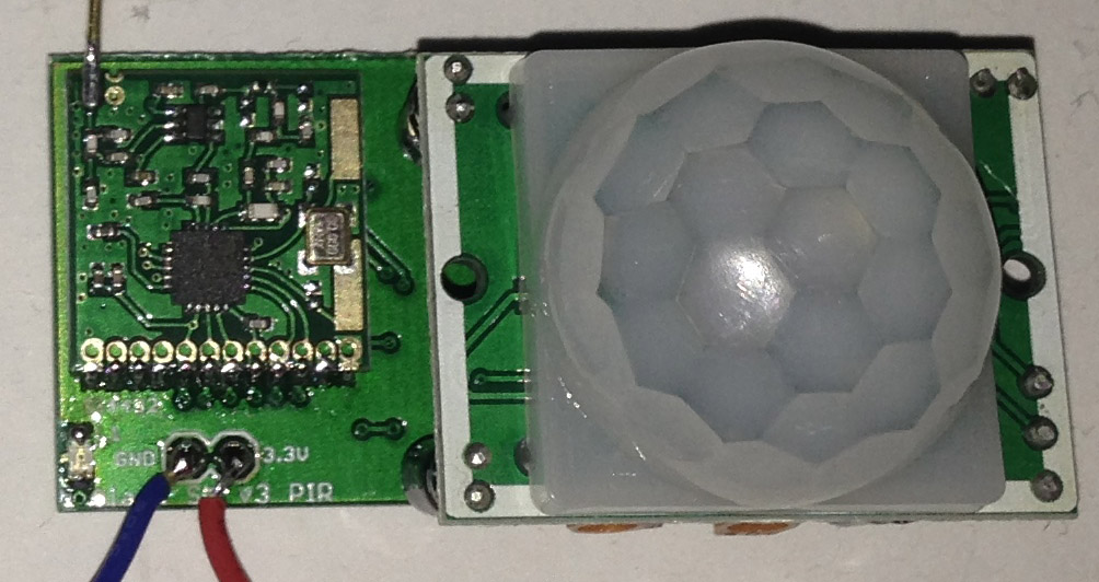
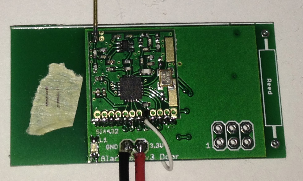
From the last part, we looked at the client/server interaction, server communication with the ESP8266, used an EEPROM to keep an event log/sensor names and added a RTC. Today we’ll add a simpple admin page to set things like the RTC, sensor names/types, email addresses for which we’ll also have the ESP8266 send us email alerts plus have a look at a PIR interference issue, various other small improvements/fixes and a quick look at PCBs and 3D printed case; a lot to cover!
The PCBs arrived a few days after I posted the last part so I built them up and tested them, it all seemed to work apart from the door sensor, 2 traces were touching each other (my mistake) so I just cut the track and re-wired it.
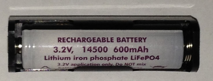
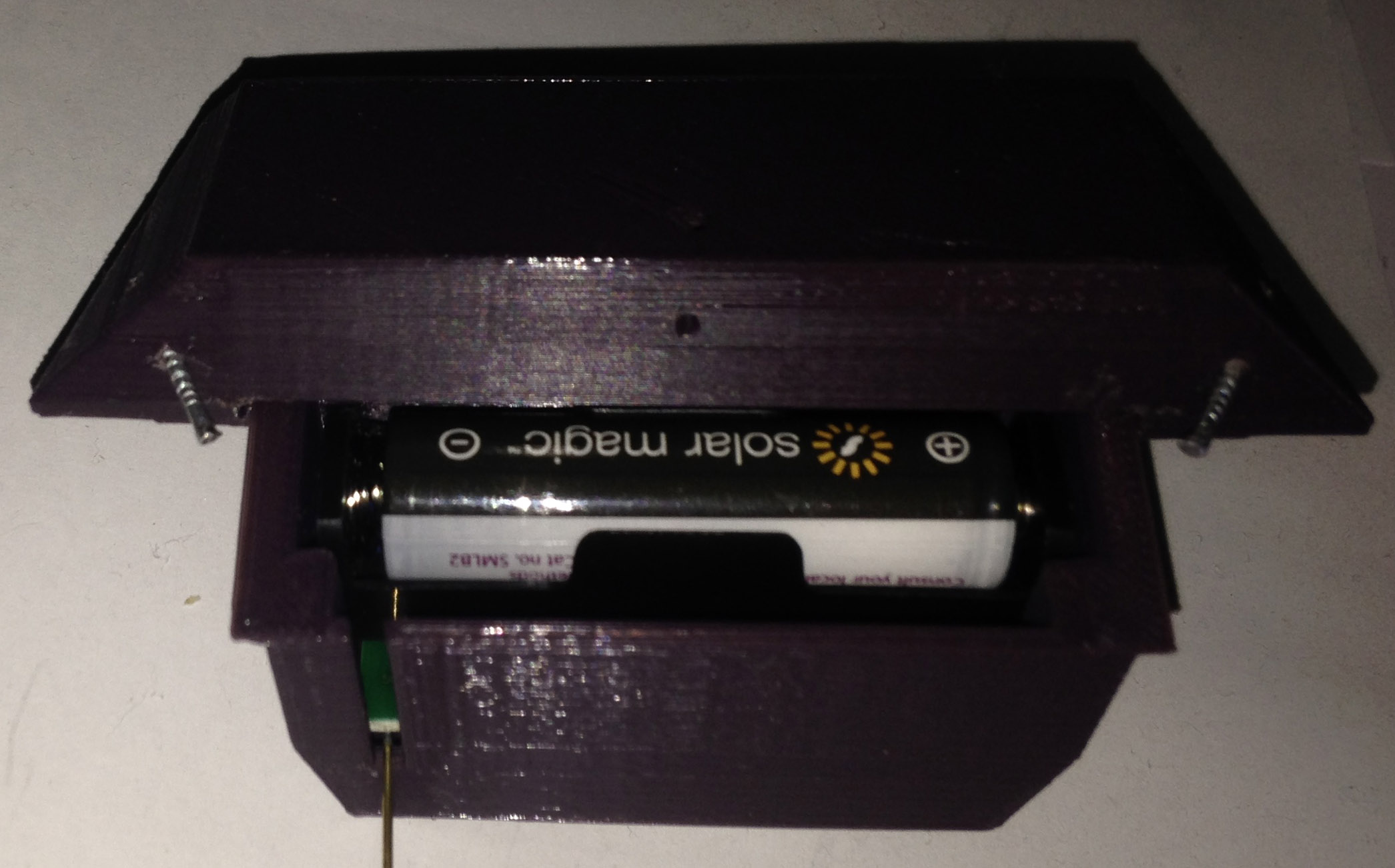
The Zippy 700mAh LiFe battery I was originally planning to go with went out of stock so I went looking for other LiFe options, turns out there is a 600mAh 14500 size which just fits a AA battery holder. If I had of re-done the PCB I could have made it a bit bigger to fit the AA holder on the back. Pricing wise, it costs a bit more ($10 for 2) but for the form factor that it offers I think I’ll stick with it.
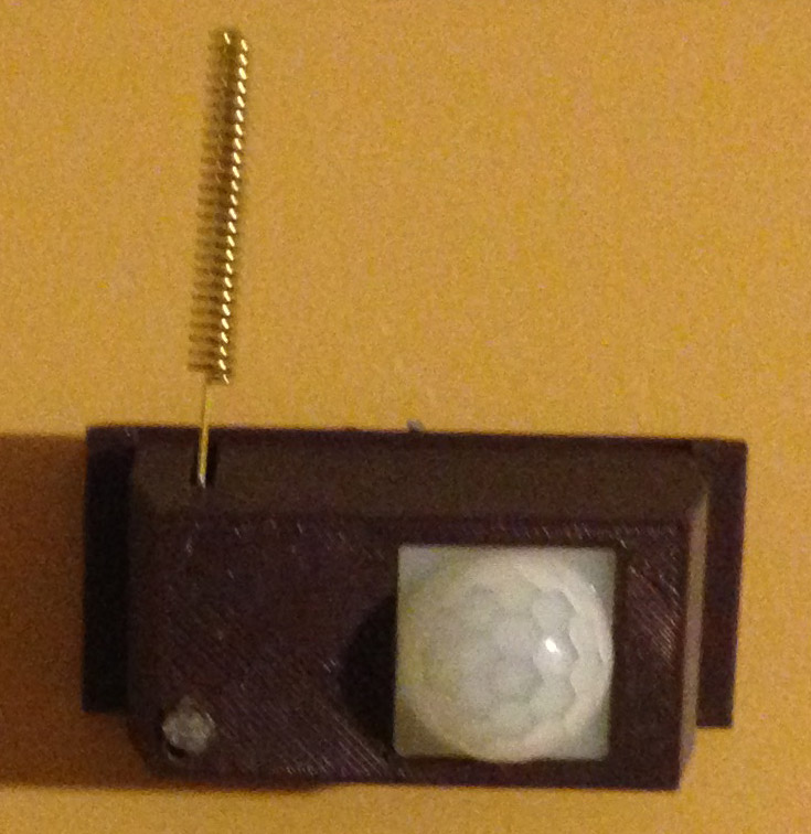
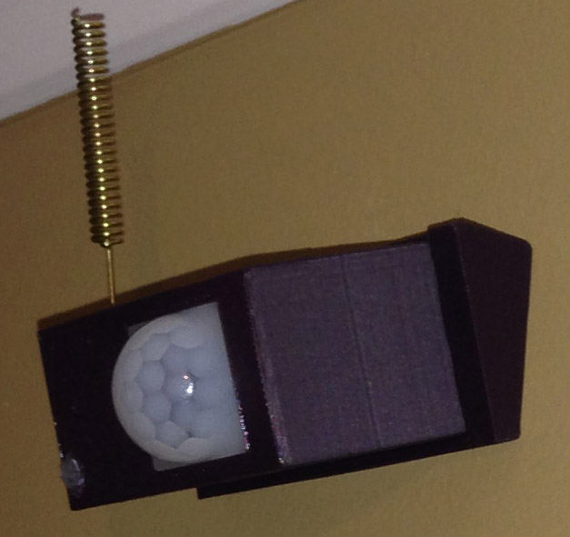
For the 3D printed case, I made something as small as possible that would fit the PCB, PIR sensor and a slot for the antenna that pokes out. I ended up putting the LiFe battery on the back of the PCB anyway with a cutout that fits it. If you look at it front on, it doesn’t look too bad, but from the side, it does look a bit bulky but it’ll do. The LED is on the bottom left of the PCB, kind of hard to see with the case on; you could use transparent material but I didn’t have any, so I made a little hole and inserted a plastic light pipe which does the trick. Later on I think I’ll paint the cases.
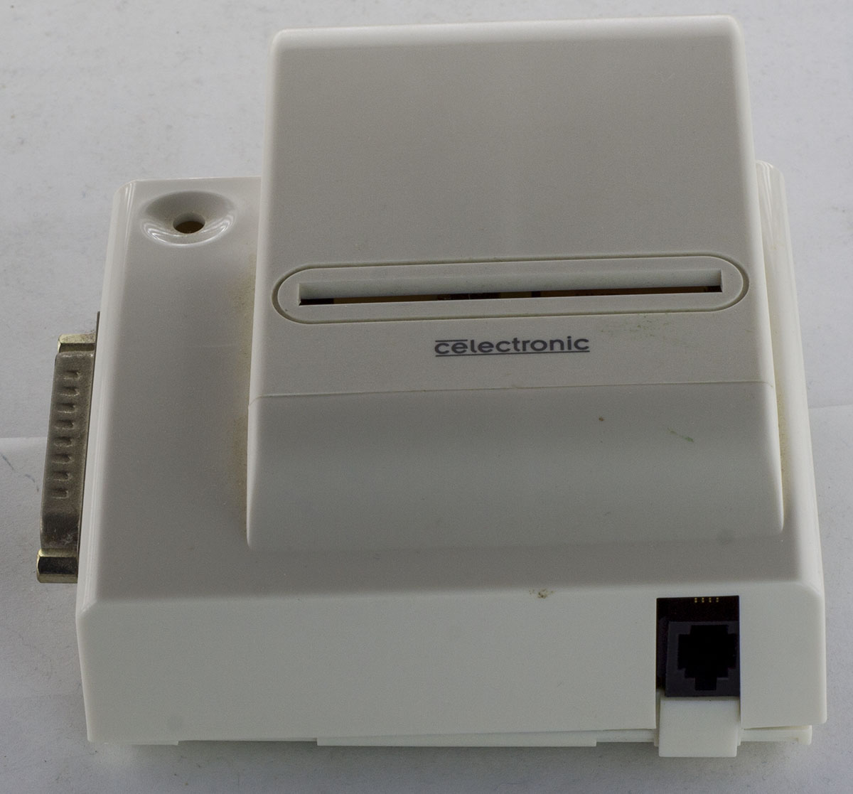
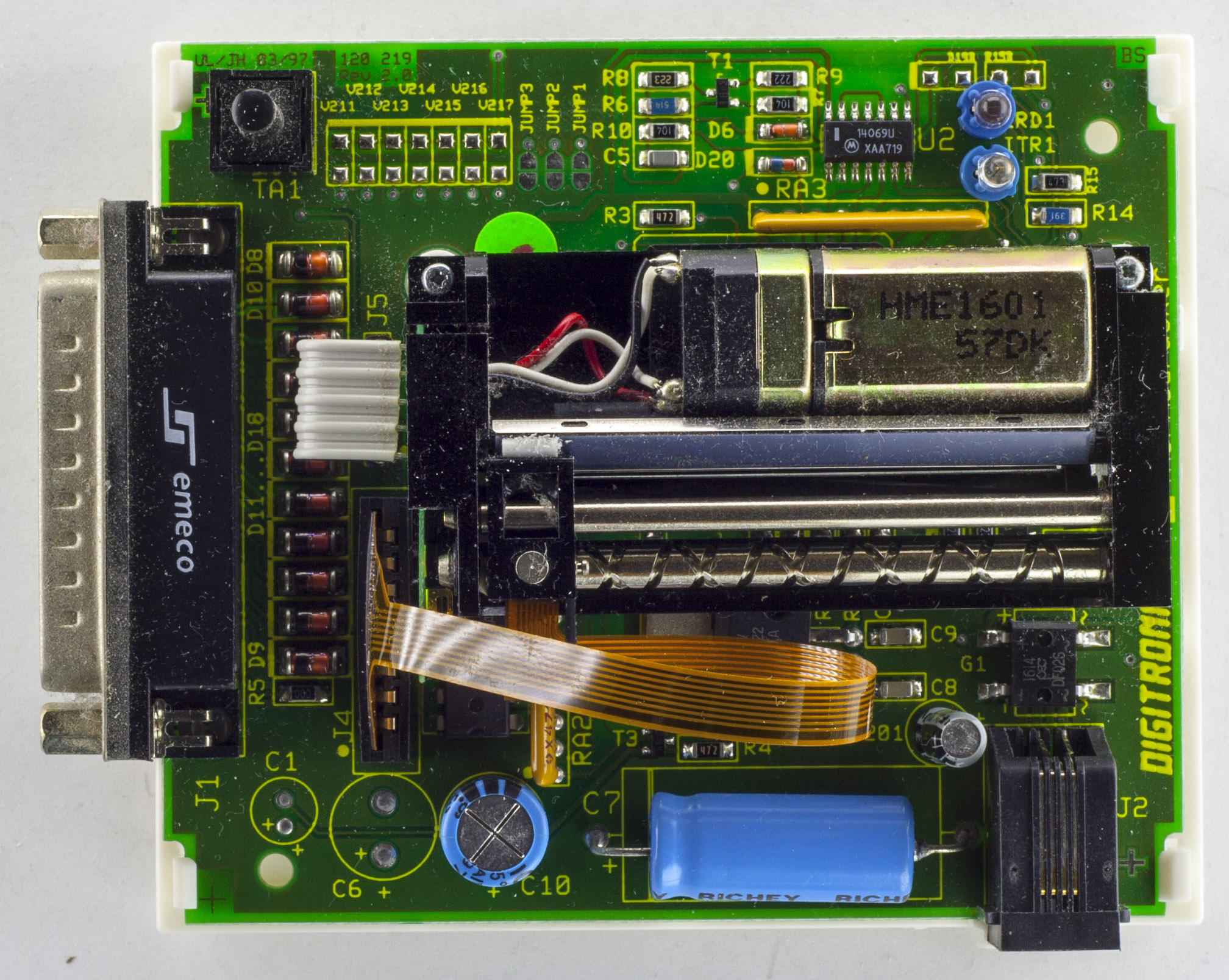
Just a quick one today, we’ll be looking at the Card Star Thermodrucker thermal printer, a low cost parallel thermal printer, I wonder how old the design is as it has a parallel port. I picked it up on Ebay about 2 years ago now to use for address labels when mailing out items. There seems to be low cost USB thermal printers for not that much more.
With the printer I got a parallel to USB cable and an overseas AC adapter rated for 9V AC at 300mA, I’ve been wanting to change the adapter for something else, so we’ll have a quick look at doing that too.
A few clips later and we’re in. We can see the thermal print head and motor sit above the PCB, held in place by 2 screws/risers, the print head connects via a flat flex cable and the motor just through some wires. There are some decent sized capacitors, Richey 1000uF 25V and Richon 1000uF 6.3V and we have zener diodes on some of the parallel port data lines. The PCB date code is 03/97!
From the last part, we looked at how to use the Atmel ATSHA204A device for random numbers / HMAC with a private key so that the client could verify what the server sends and vice versa. Today we’ll test the client/server interaction, have the server talk to the ESP8266, add an EEPROM to keep an event log/sensor names, RTC plus I’ll briefly touch on FHSS for the Si4432.
For the client, we can stick with the ATtiny84 (or ATtiny841 which I have a few spare) and for the server I’ve gone with an ATmega168, both the client and server have an ATSHA204A device with the same private key as each other. In terms of security, it’s not the best if physical access is obtained, a client could be taken away and still have access to the system and act as a server, the best thing to do in that case would be to re-key the private key.
Client side
// Generate random number
atsha204a_command_random_number(DELAY_WDT);

// Check in
RH_RF22_resetFifos();
RH_RF22_txHeaderRequestType = CHECK_IN;
RH_RF22_send(randomNumber, 32); // Send 32 byte random number ([0] will be changed by the server)
RH_RF22_clearInterrupts(); // Must be cleared here as it goes low before the packet is sent
RH_RF22_wait_for_transmit();
RH_RF22_sleep();

// Wait for server to do nonce and HMAC
watchdog_sleep(T128MS);
watchdog_sleep(T32MS);
watchdog_sleep(T16MS);

// Wait for packet to match our address
if (wait_for_valid_packet()) {
After combining the ATSHA and Si4432 code, we can have a look at the client check in. We run the random number command function for which I’ve added the option of using _delay_ms or the watchdog timer for low power consumption. We do the usual clearing of FIFOs and interrupts, set the request type as check in and send the random number to the server.
Strangely enough if you clear the interrupts before you load the packet and turn the transmit mode on, the Si4432 will set the interrupt low straight away so it will seem like an interrupt occurred before the packet was even sent. Turns out you have to set it right after you turn the transmit mode on and it works fine. Edit: This is because we need to reset Register 06h. Interrupt Enable 2 to 0, default is 0x03 (Enable Chip Ready and Enable POR)
I’m now using Si4432 interrupts when receiving or sending a packet which allows the ATtiny to sleep during that time and wake up on a pin change however we don’t want to keep the Si4432 listening for too long. After some trial and error I found that using the watchdog to sleep for 128ms + 32ms + 16ms gives us just the right delay for the server to generate the HMAC and for us go into receive mode when its close to sending us the HMAC. I measured that it takes about 9ms after the packet is loaded for the packet to be sent (i.e enpksent is 1).
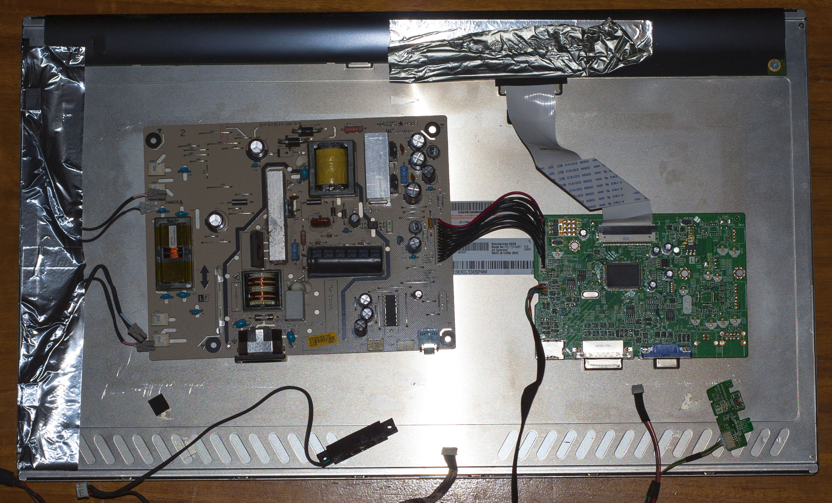
Today we’ll be looking at the BenQ 21.5″ E2200HD LCD Monitor which features a 1080p display, HDMI / DVI / VGA inputs, speakers and a headphone jack. This one stopped working one day, I’ve had it for 8 years so decided to take it apart to see what was wrong.
(forgot to take some pictures of it before I took it apart, so here’s a stock image)
After a couple of tough clips and removal of the stand, we’re in. There was a metal cage holding the power and logic boards but it was just stuck on with some shielded tape, no screws whatsoever which was odd. Powering it up by the power button, I can see the power LED turn on for a fraction of a second, does this 2-3 times before it no longer lights the LED.
From the last part, we looked at using the Si4432 module for communication between the sensors and server with the ESP8266 Wifi module as our web server. Today we’ll look at the Atmel CryptoAuthentication ATSHA204A device which will let us use truly random numbers and use the HMAC function with a private key (stored securely on the device) which means no hashing libraries will be required for the ATtiny.
The way I intend to use the device is for it to return a 32 byte random number which we can change 1 byte of so the server and client can communicate with that 1 byte, feed it into the device which will generate a HMAC from that random number and a private key.
I’m using the I2C version which should be quicker to access and easier to use than the the 1 wire version, should save us a little bit of battery life too. Before we hook it up to the ATtiny, we need to test it so we’ll be using the Arduino, there are one wire library examples out there but none for the I2C version. Atmel also has some libraries available for the CryptoAuthentication product suite however there was a lot of functions and jumping around so the only code I used from that library was the CRC function.
The device contains 3 zones:
– 16 data slots where you can load a 256bit key to each slot
– Configuration zone includes allows you to set how the data slot keys can be used, whether the keys can be read/written, a counter to provided limited use of the data slot keys, the unique serial number and programmable I2C address to name a few.
– One time programmable (OTP) zone contains 64 bytes that can be used as read only memory.
The configuration zone and data slots/OTP can be locked to block any writes to them, this is useful if you don’t want keys re-programmed and disallow how each data slot can be used. In order to write to the data slots, the configuration zone needs to be locked.
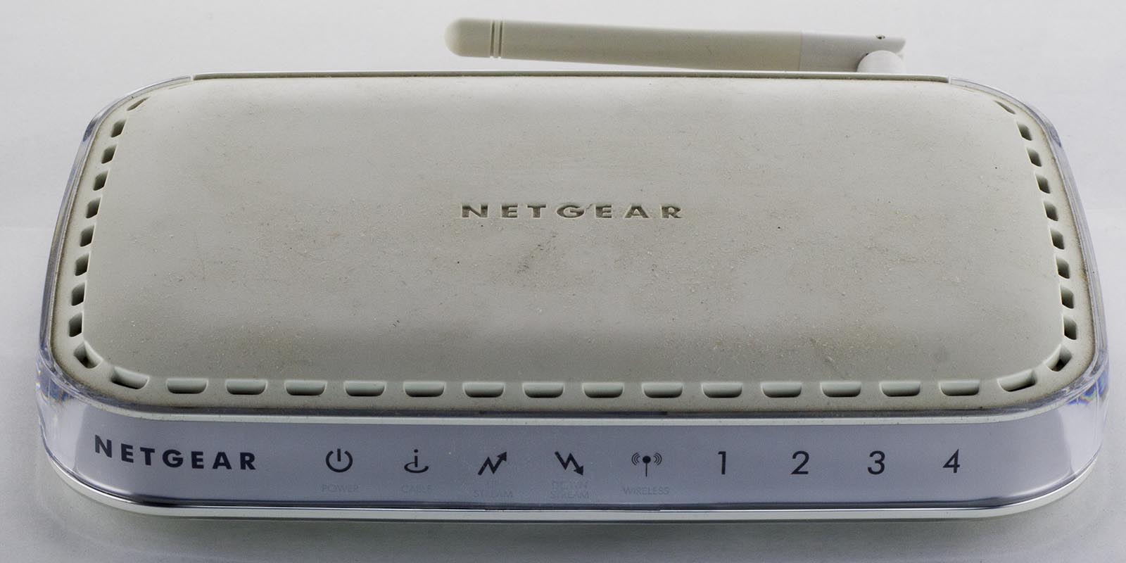
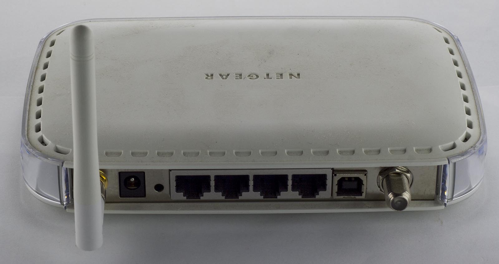
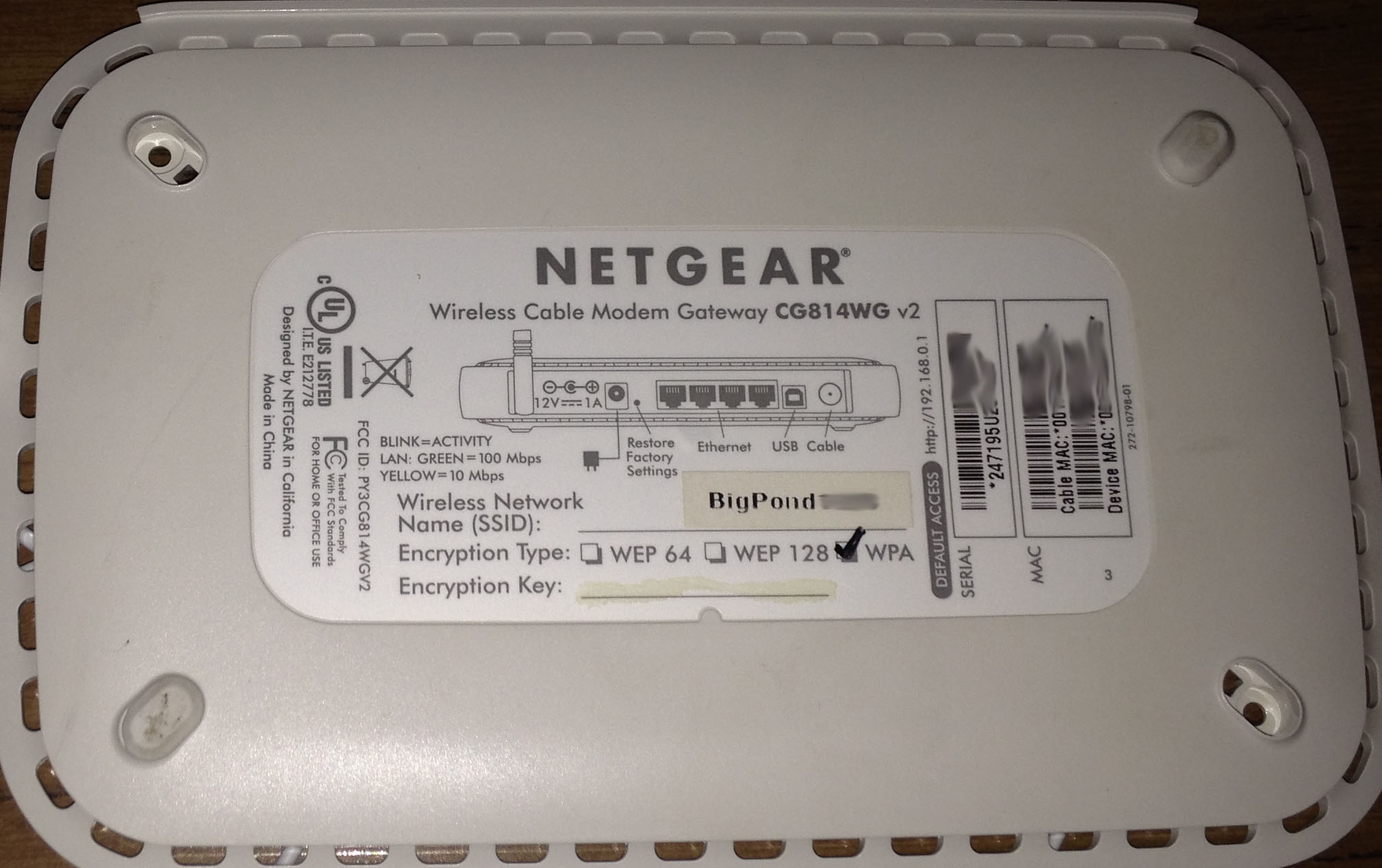
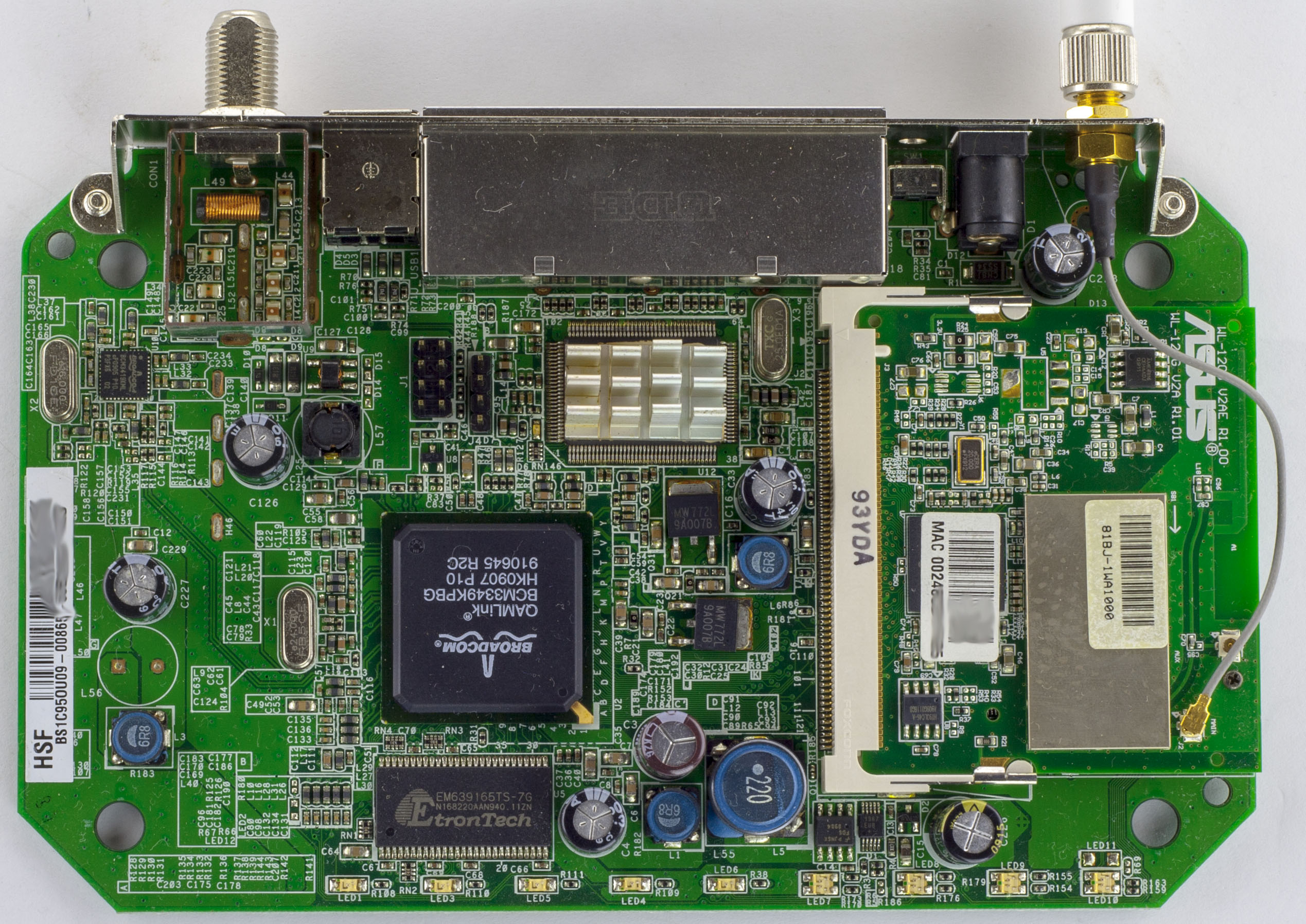
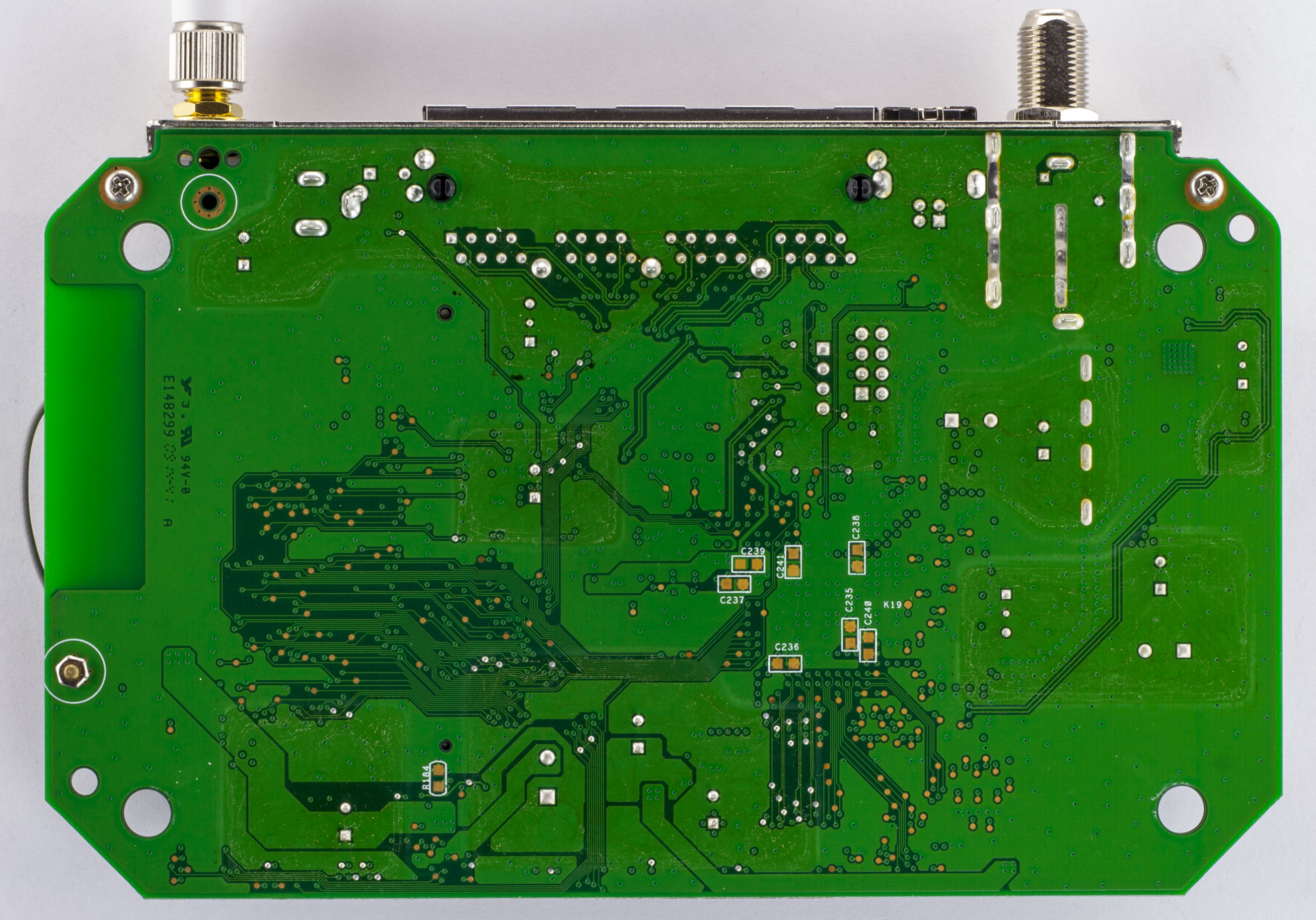
Today we’ll be looking at the Netgear Wireless Cable Modem Gateway CG814WG v2 which is a cable modem/router with 4x 10/100 network ports, 1 USB port and 802.11b/g Wifi.
Four screws later and we’re in
We’ve got a 2 chip solution with only a heatsink needed for the Ethernet chip and the usual Mini PCI wifi card (which seems to be common for devices of this time). Only 1 DC-DC converter on board with a large 22uH inductor plus there are some noticeable 6.8uH inductors sprinkled around too, the caps are branded OST / TEAPO. We also have some 4×2 pin and 4 pin male header near the main chip. The PCB date code is 14th week, 2009.
This project has quite a few SMD parts, soldering them by hand can take a long time so I decided to give stencils a go as I hadn’t used them before. I ordered one from OSHStencils for the top side, it came within 1-2 weeks which was good. I played around with how to align the stencil, applying the solder paste, etc, after a few tries I got relatively good coverage of the pads, placed the components, soldered them with the hot-air rework station and it worked out nicely.
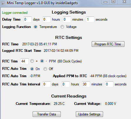
We also have a GUI now which automatically picks up the device so you can easily connect/disconnect them without closing and re-opening the program.
I built a few more of them up with two different RTC capacitors, 7pF and 8pF, both of them seemed to worked well and the 8pF one almost didn’t need any digital trimming. I popped them in the freezer but both of them eventually stopped working after a few hours so that’s no good so it’s back to the 6pF caps.
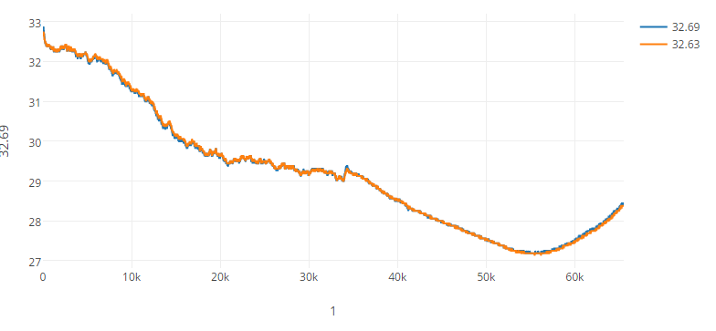
A quick comparison between 2 loggers (top) and 3 loggers (bottom – in freezer, something isn’t right with our freezer, pretty hot day when the test was run) placed right next to each other shows that temperatures between them were very close to each other so the TMP102 temperature sensor is pretty accurate.
From the last part, we decided on our design – use a DC-DC to pre-regulate the voltage feeding into the LM350 linear regulator that’s controlled by a PNP transistor and we’ll use a N mosfet with op-amp for the current limiting. Now we’ll add in everything else – the displays, ADC, DAC and Digital pot, it’s taken a while to reach this point.
I started checking for the parts and came up with the following:
I like this DAC because you can either use VCC or any voltage from 0.01V as the reference voltage which can be buffered (could use resistor dividers to set voltage) or unbuffered. This is going to be very handy for setting the current which passes through the 0.1 ohm resistor. We will need 2x of this DAC, you can purchase different address options (can be harder to source).
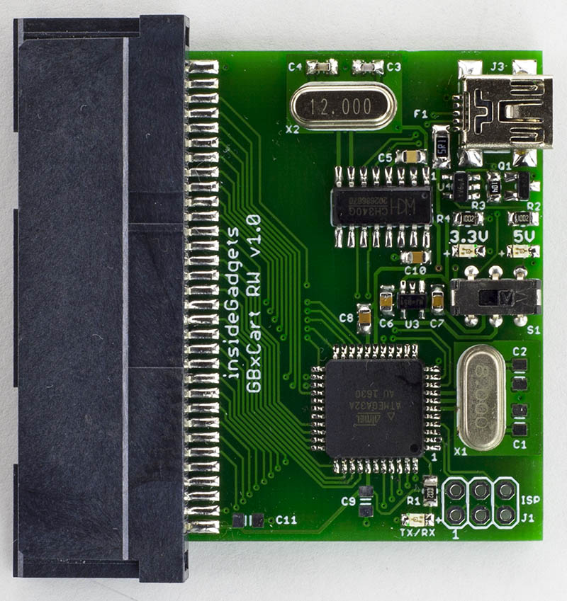
GBxCart RW v1.0 has now been released and is available for purchase (I decided to rename it from GBxCartRead as we also do writing too). The PCBs arrived and everything worked however I got the switch connections reversed, so changing it to the left means 5V is selected and to the right means 3.3V is selected, so just be extra careful when using a GBA cartridge.
// Set pin output as low
else if (receivedChar == SET_OUTPUT_LOW) {
	char portChar = USART_Receive();
	usart_read_chars();
	uint8_t setValue = strtol(receivedBuffer, NULL, 16);

	PORTD |= (1<<LED);
	if (portChar == 'A') {
		PORTA &= ~(setValue);
	}
I’ve decided to add raw I/O access to the Gameboy Slot pins through the COM port as some users may not be able to update the ATmega with new versions, so if there were any carts I would like to add support for, we could control the all pins from the software, it’ll be slower but it will work.
AdvanceVGA – Play your GBA on the big screen! Swap out the LCD for our board, solder some wires, connect 5V USB and VGA and you’re ready to go.
GBxCart RW allows you to backup GB/GBC/GBA ROMs, save or restore game saves and re-write supported flash carts. Mini RW option available for GB/GBC only.
Wireless Gameboy Controller – Use your Gameboy, mGB, GBC, GBA, GBA SP, GB Micro, NDS and NDS Lite as a wireless controller on Windows, Linux, Raspberry Pi, etc, and on your NES, SNES, N64, Gamecube and Wii.