A little while ago I picked up a low cost 3D printer, the Malyan M150 and after printing all sorts of things from Thingiverse, I decided to move over to designing cases for my projects which was the original intent for the purchase.
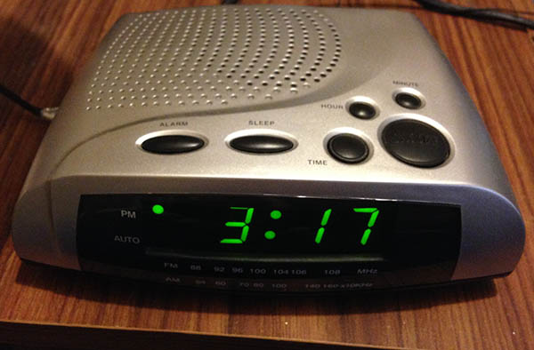
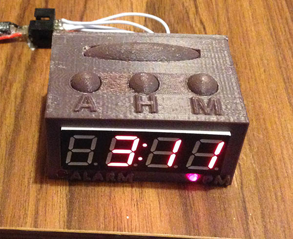
(old alarm clock – 16 x 11 x 5cm) (new alarm clock – 6 x 4 x 3cm)
I still use a nightstand alarm clock as a backup just in case I don’t wake up from my phone alarm however the current alarm clock that I’ve had for years is a bit too bright at night so I end up having to cover it up or move it so I’ve decided that I might build my own which would allow me to turn off the display or dim it significantly by pressing the snooze button.
(video showing functionality)
The clock will be minimalistic, it will have 4 buttons: snooze/display off/on, alarm on/off/set alarm time while held down, hour and minute, LEDs for alarm on & PM indicator and just have a little buzzer as the alarm which we’ll PWM to a suitable tone of our choosing. We’ll use a medium sized 4 digit 8 segment LED display that I had bought from Ebay some time ago (ZTT-5461BS, common anode), the MCP7940M RTC and an ATmega48 which I had lying around which will have just enough I/O pins for our needs. I’m able to re-use some code from the LED clock project and I’ll also try out the RTC alarm functions.
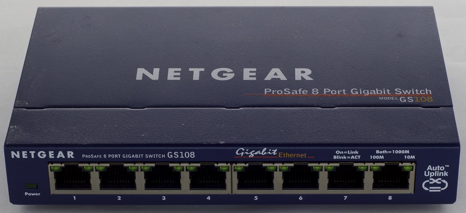
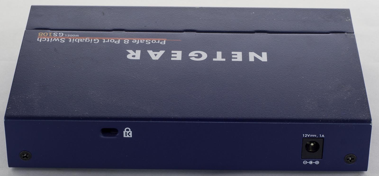
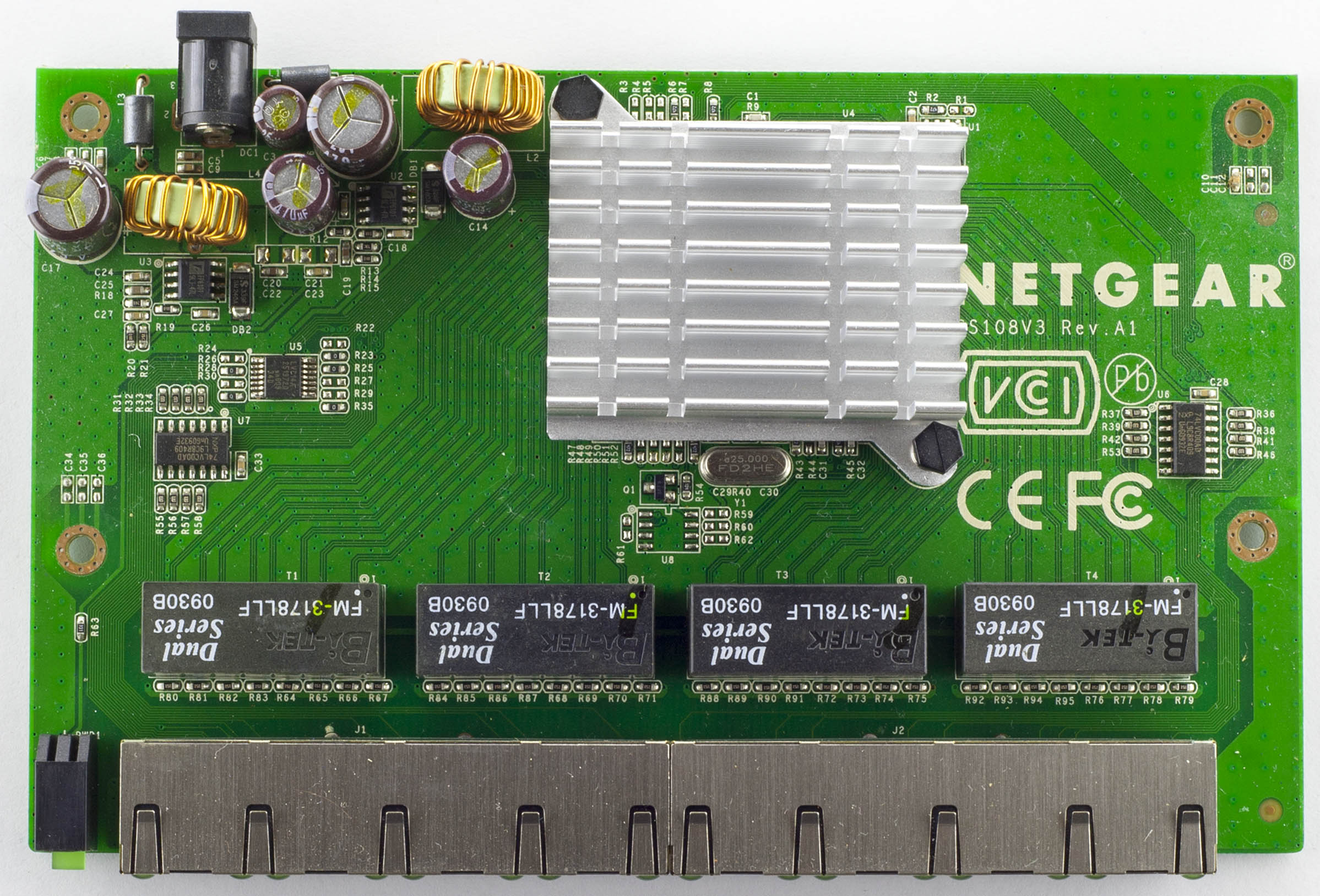
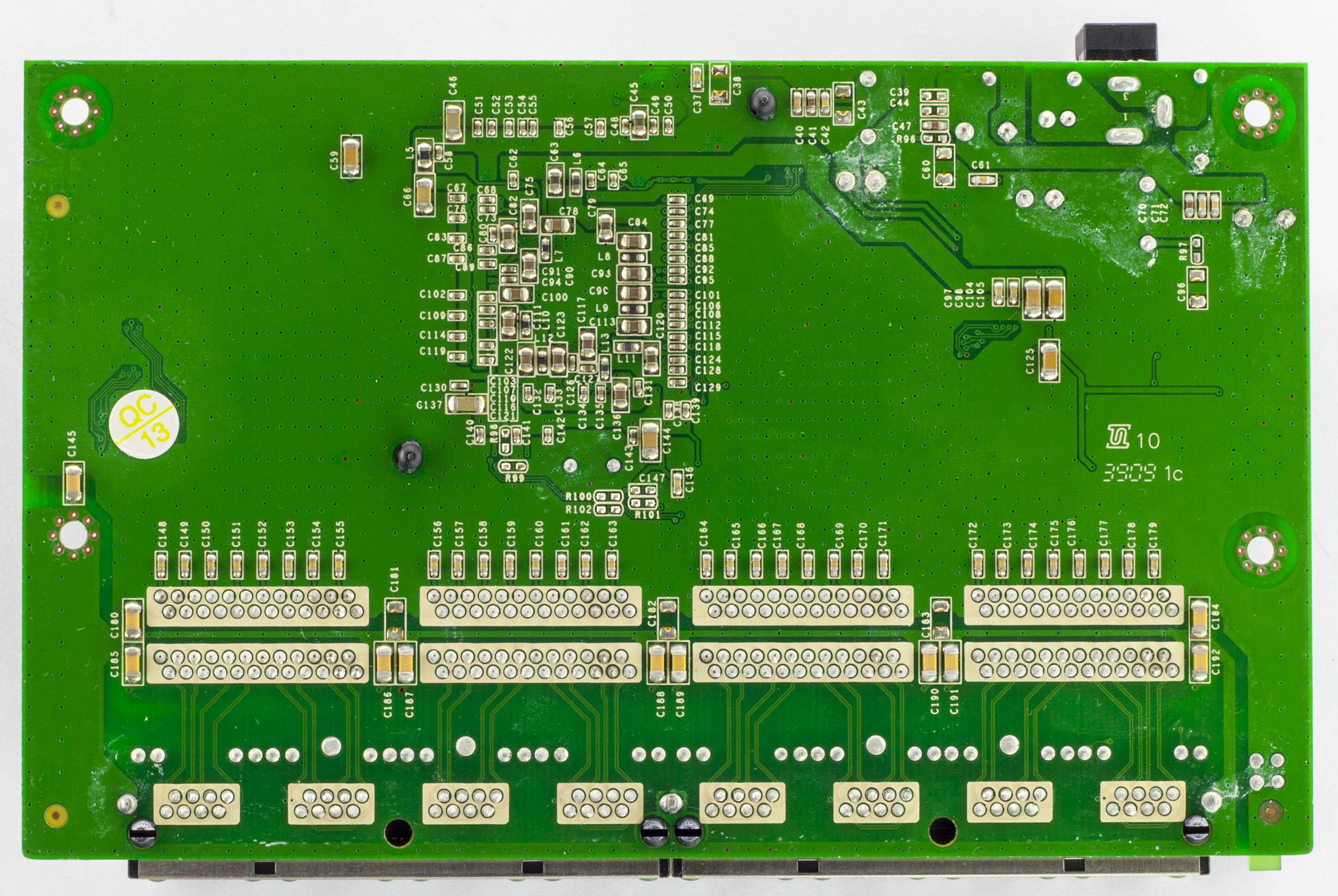
Another quick one, today we’ll be looking at the Netgear ProSafe GS108 8 Port Gigabit Switch which is an unmanaged 8 port gigabit switch and has a little Kensington lock on the back.
Two screws later and we’re in.
There are a couple of logic chips hanging around which isn’t too common on low port switches, a pretty decent heatsink on the main chip and a good amount of via stitching. PCB date code is 39th week, 2009.
From the last part, I talked about some of the ideas I had for the Alarm system v3, two of which we’ll look at today, using the Si4432 module and the ESP8266 Wifi module.
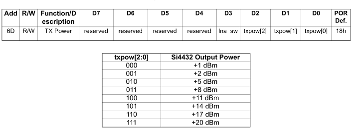
The Si4432 module is has an adjustable frequency range of 240MHz to 930MHz so you could use any frequency you wanted but to keep it legal I’ll use a frequency between 433.075 to 434.775MHz. The input voltage is 1.8V to 3.6V, you have the option to adjust your transmit power from 1dBm to 20dBm (17mA to 85mA), we have RSSI available and have TX and RX FIFO buffer of 64 bytes. An interesting feature is that you can disable the FIFO and access the RX/TX of the chip in direct mode in real time, something that could be useful for streaming applications. We can also have interrupts on RX received and TX transmission complete.
I bought a couple off Ebay, used the RadioHead RF22 library and hooked up the TX and RX to 2 Arduinos and it worked well, the default frequency is 434MHz. Range wise I didn’t have any problems in the garage or outside.
I started increasing the output power and once I reached anything higher than 8dB, the receive text became corrupted, adding a 100uF capacitor on the TX helped and then I added a 10uF capacitor on the module itself to reach 17dB but it occasionally still resulted in corrupted text, I think I’ll still to 8dB or less.
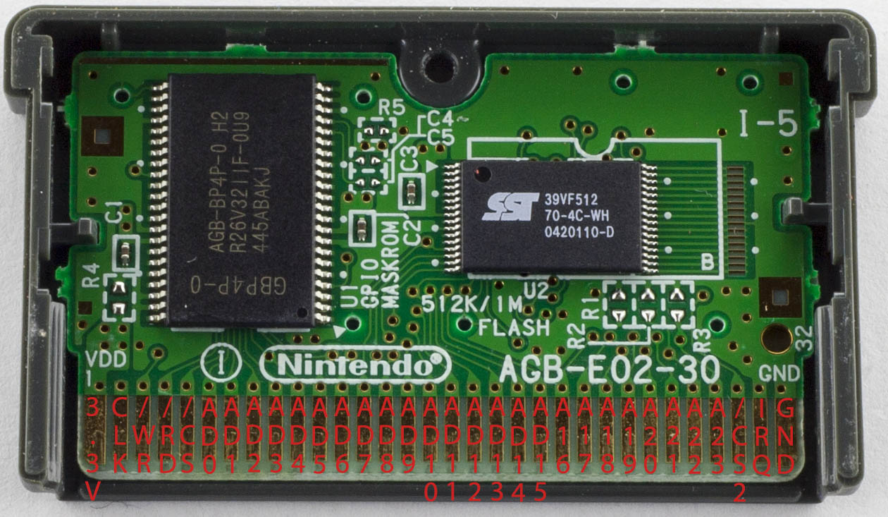
From the last part, we switched to the CH340G USB to serial converter which gave our read speeds a bit of a boost, we looked at reading the GBA ROM, SRAM reading/writing and how to automatically determine ROM/SRAM sizes. In this part, we’ll cover EEPROM read/write, Flash writing and determining EEPROM size and checking if we have SRAM or Flash.
I was previously looking at the ATmega32A which I’ve received and was able to switch to, it has just enough pins, with 2 pins to spare, one will be an LED pin and the other will detect the 5V/3.3V switch so we know whether we’ll be interfacing with the GB or GBA.
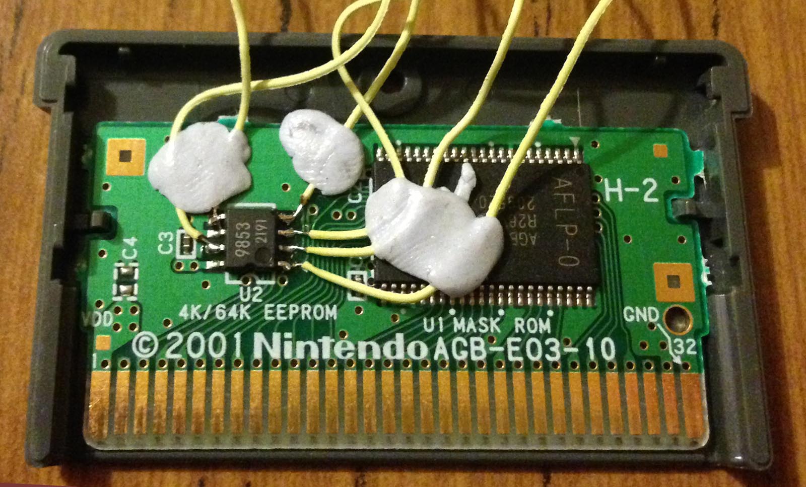
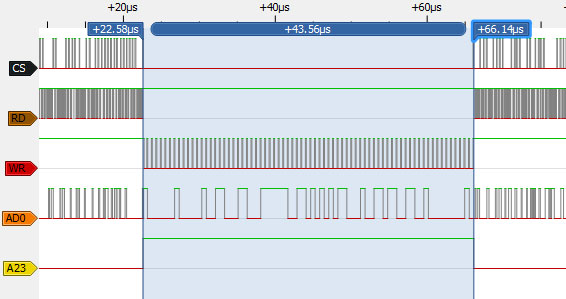
On to the EEPROM, I found the GBATek page which gives a explanation on how to address the EEPROM and what to do when reading/writing so it’s a good and simple resource to use though I wanted to see for myself how the GBA interfaced with EEPROM with any timings I need to consider. I broke out the logic analyser on the Fila Decathlon game which uses a 4Kbit EEPROM.
Writing to EEPROM
Thankfully the game allows you to save to the EEPROM after the first event so I was on my way. For a write, we can see that CS goes low, RD goes high, WR is the clock line as we drive the EEPROM serially, AD0 is the data and A23 goes high. If we were to read from the EEPROM, the RD pin would be the clock and the WR pin would be high.
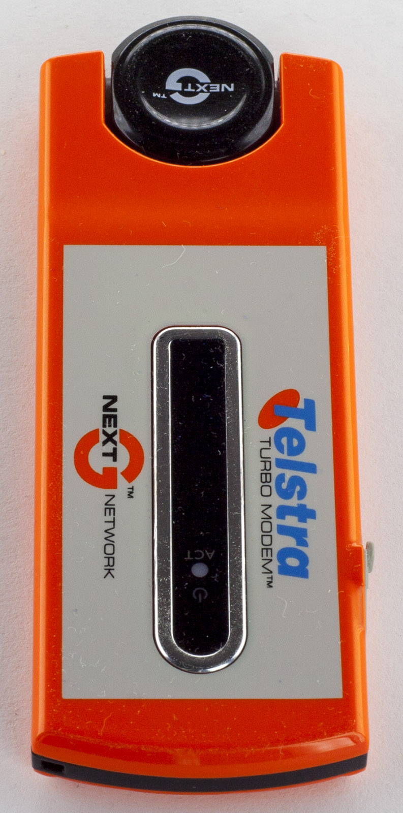
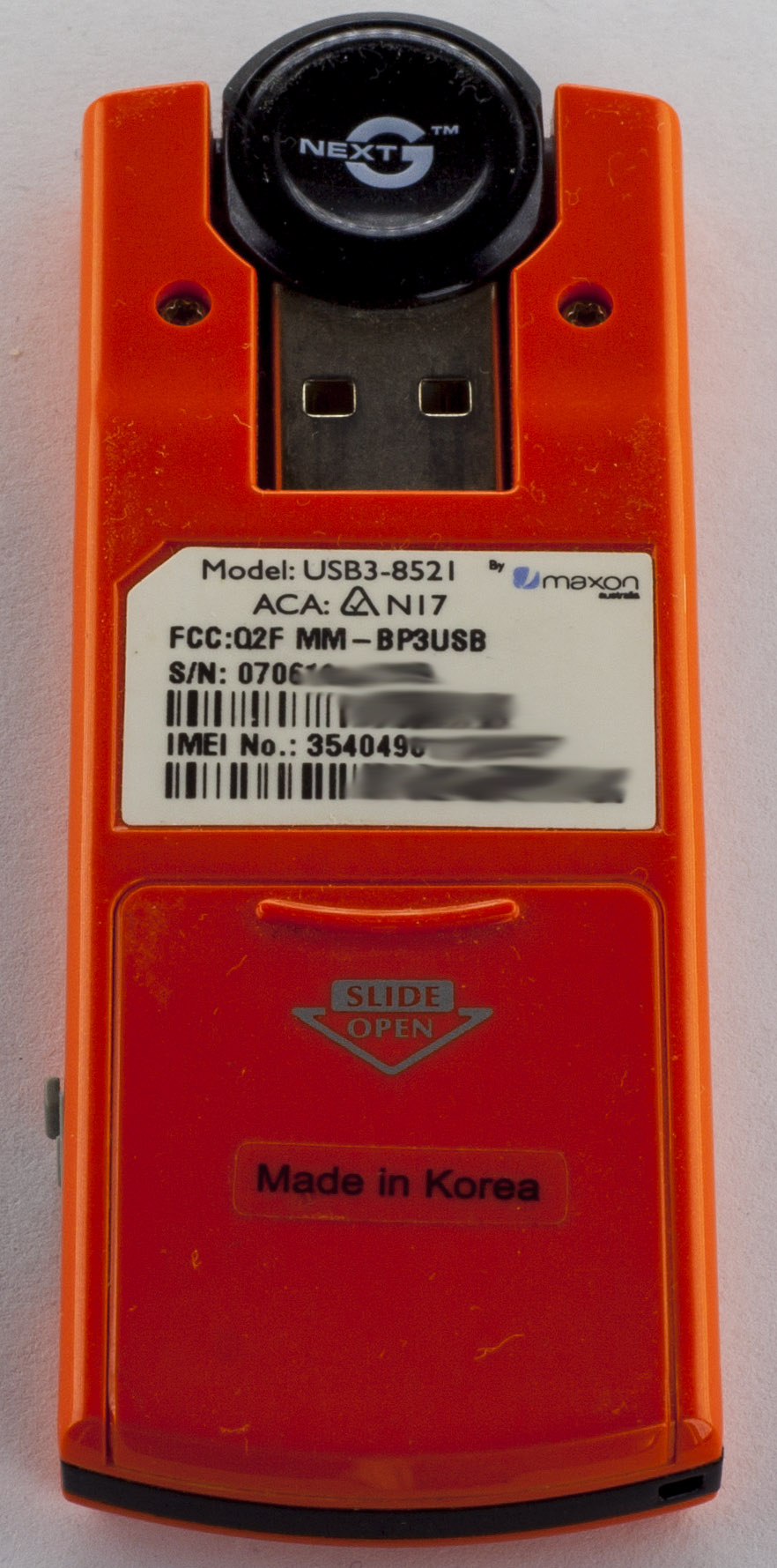
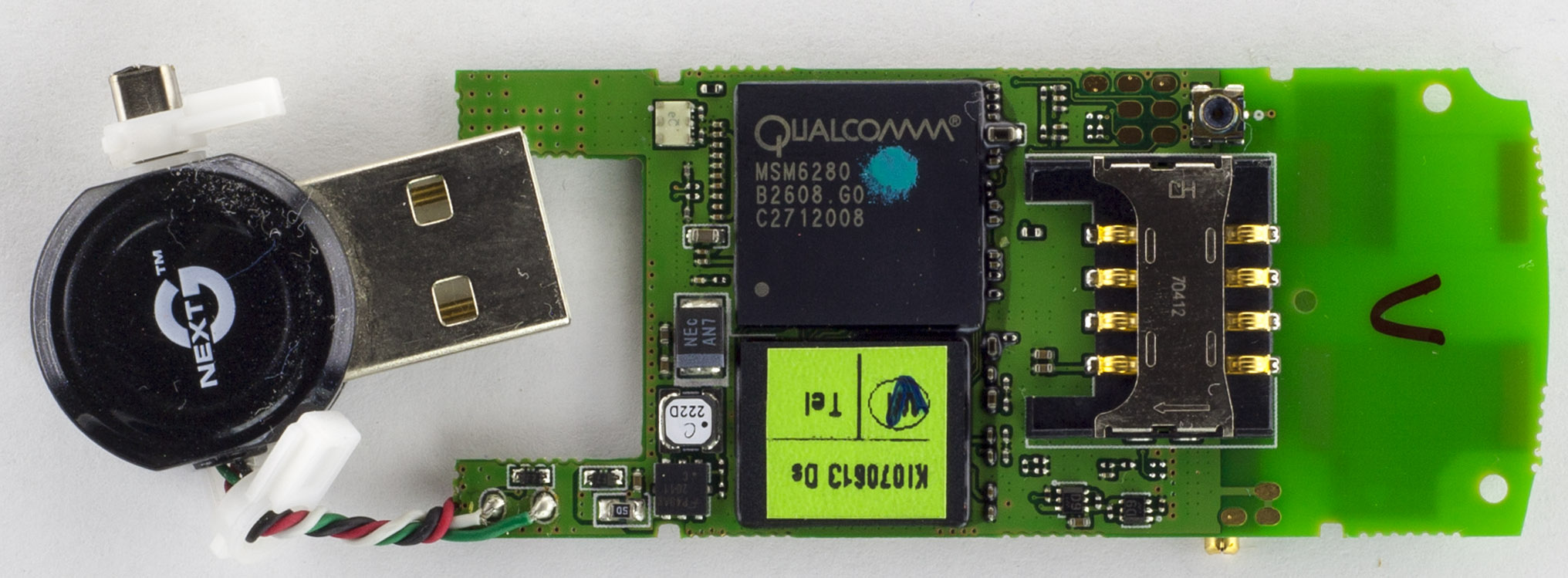
A quick one today, we’ll be looking at the Telstra NextG Turbo USB Modem (USB3-8521) which is a USB modem using the NextG network to have Internet on the go. It has a slide where the SIM card goes and you can connect an external antenna.
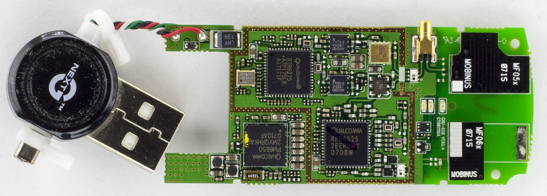
Four screws later and we’re in.
The USB connector is just attached via the 4 twisted wires which seems like it would hold up to some movement. We have 2 different Mobinus branded PCB antennas, the 2 white RF output transistors nearby and there is an external antenna connector on the bottom for the other antenna. There is a guard trace around all the RTR and RFR chips but no need for a RF can it seems. This board is a complete Qualcomm solution board (apart from the memory).
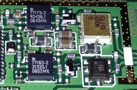
There are two small chips next to the RTR chip, then there are 2 small SOT23 (or smaller) 4 pin looking devices, then a ceramic package which is likely to be gold plated and another custom package next to it.
From our last part we received our PCBs, did some RTC crystal testing, some of the results that I couldn’t explain was that it drifted a few seconds some days whilst my home clock that used the same RTC didn’t. After a lot more testing (weeks, ouch!), it turns out that my computer was the cause, its clock changes by a few seconds every few hours, even though I had it syncing up in the mornings, so I switched to using an online time website. After a bit of calibration, I left it running for 10 days and it’s only 1 second slower so I’m happy with that result.
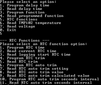
I was previously thinking about adding in a RTC auto trim function to trim based on temperature which I thought might help to resolve the initial issue I had but it wouldn’t have actually done much (due to my timing issue), in the end I implemented it and it will work when it’s logging or not plus now the RTC related functions in the interface program have a dedicated section. As per the crystal PDF specs, they had a formula for this purpose: -0.035 x ((T – To) x (T – To)). We can program in the interval (seconds, minutes, hours or days) for the auto trim function to run, whether we want it on or off and a few options to read back the PPM trim value calculated and how it would affect the current static RTC trim.
From the last part, we looked at the design for the new GBxCartRead project which will read the Gameboy & Gameboy Advance ROM/RAM. For the data transfer between the PC and ATmega I went with the V-USB ATtiny85 method (for testing the communication method incase the USB to serial chip didn’t work) and was able to re-use some of the GBCartRead code to successfully read Gameboy cartridges though it was quite slow.
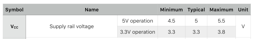
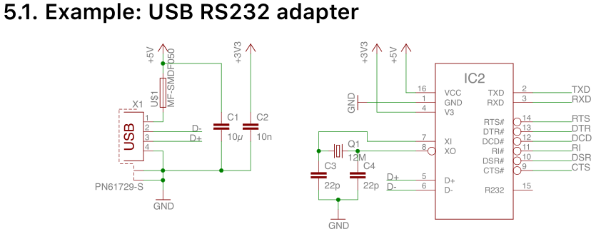
The faster method for data transfer is using a USB to serial converter chip like the CH340G, it will mean less parts overall and should result in a faster speed, if it works. The CH340G looks simple enough to control and hook up, it can be powered by 5V or 3.3V which is good for us as we’ll have to switch between the GB and GBA. It needs a 12MHz crystal, a few capacitors, a polyfuse (if you want), the USB+/- lines and the TX/RX lines, the other lines we can ignore.
I hooked it all up without the crystal capacitors (I usually do this with AVR chips and they work fine) but it didn’t work, only when I touched the crystal pins would it work, add in the 22pF capacitors and it works fine. I performed a quick loopback test at 1Mbps and that also passed. Now we just need to change a bit of our ATmega / PC code to work with it, I’ll be using the Teuniz RS-232 library like I did in GBCartRead. After a quick test, reading 128KB of ROM now only takes 4 seconds!
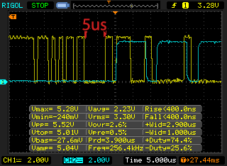
One thing we do need to be careful of is if the PC sends 64 bytes of data at once, the CH340G will dump all this data to the ATmega as quickly as possible, there is about 5uS of dead space where the ATmega can do something else (if you are curious the blue trace shows when the ATmega receives a USART packet and falls once the SRAM write is performed). Instead of doing the write command after each byte received when writing like I was doing, I will read all 64 bytes on the ATmega, perform the task and then send an acknowledge byte back.
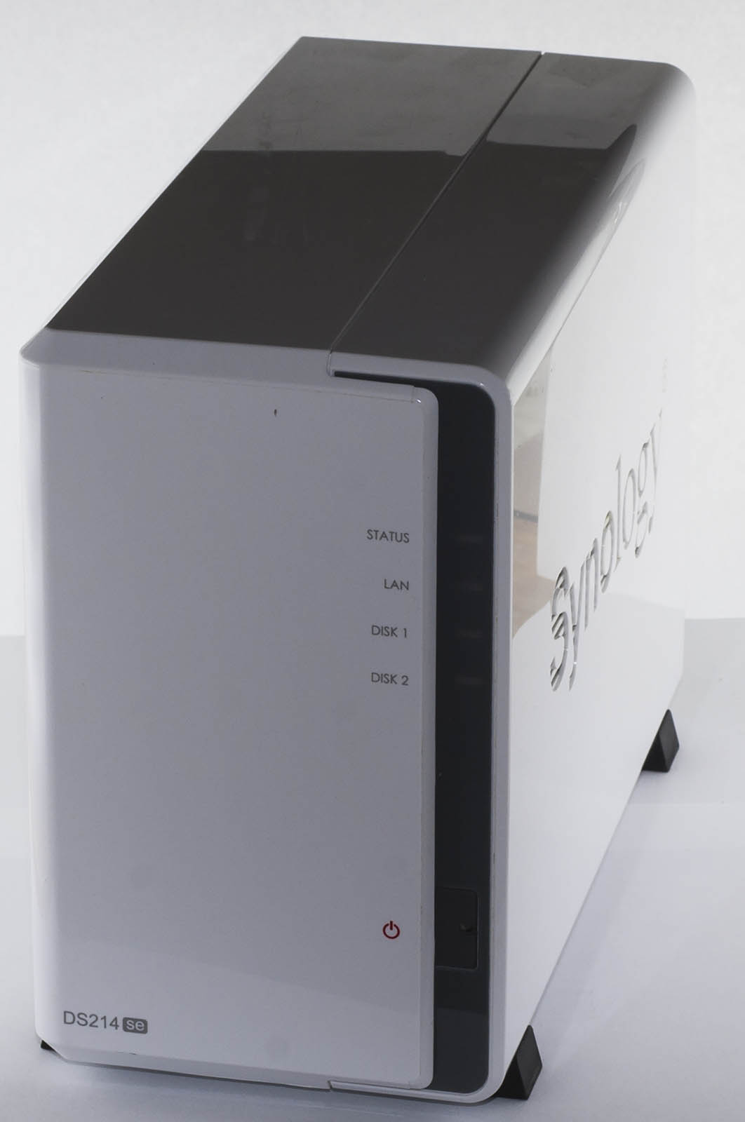
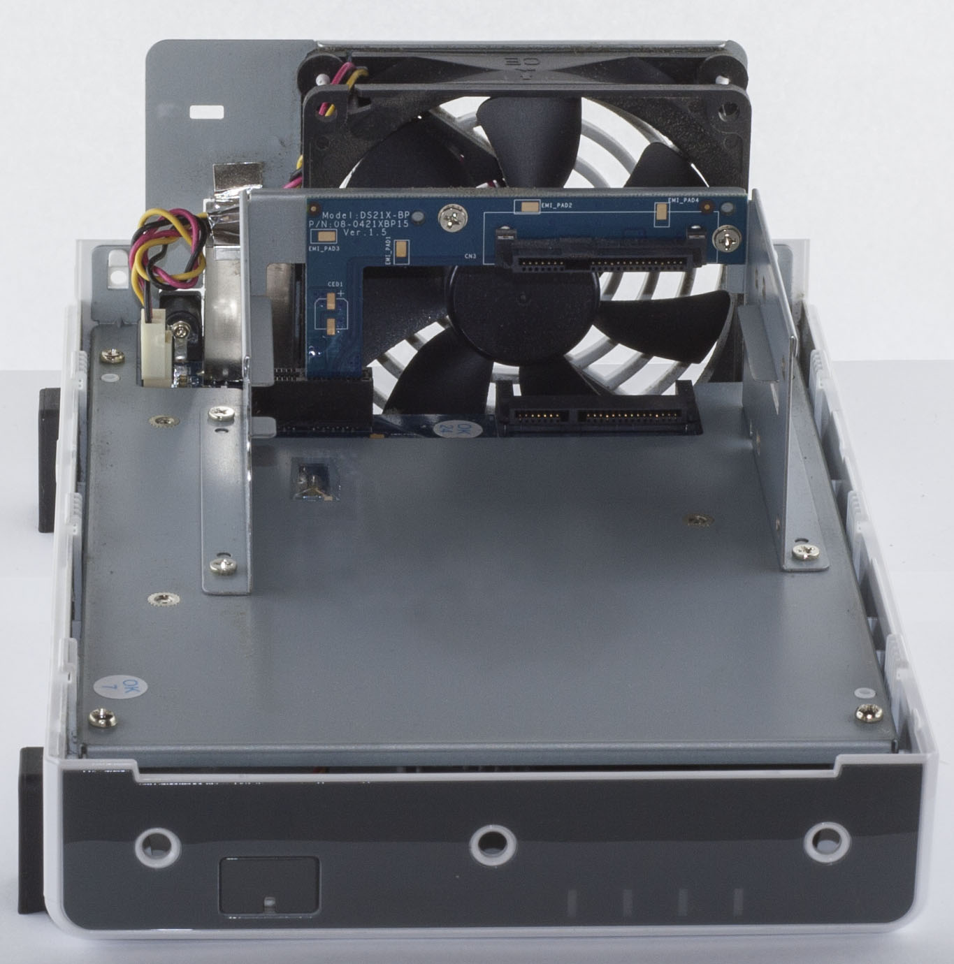
Today we’ll be looking at the Synology DS214se Dual Bay NAS (Network Attached Storage) which is similar to the single bay DS112J NAS except that this one has 2 hard drives to allow for RAID1/0, it has the standard Gigabit Ethernet and 2x USB 2.0 ports.
Two screws later and we’re in.
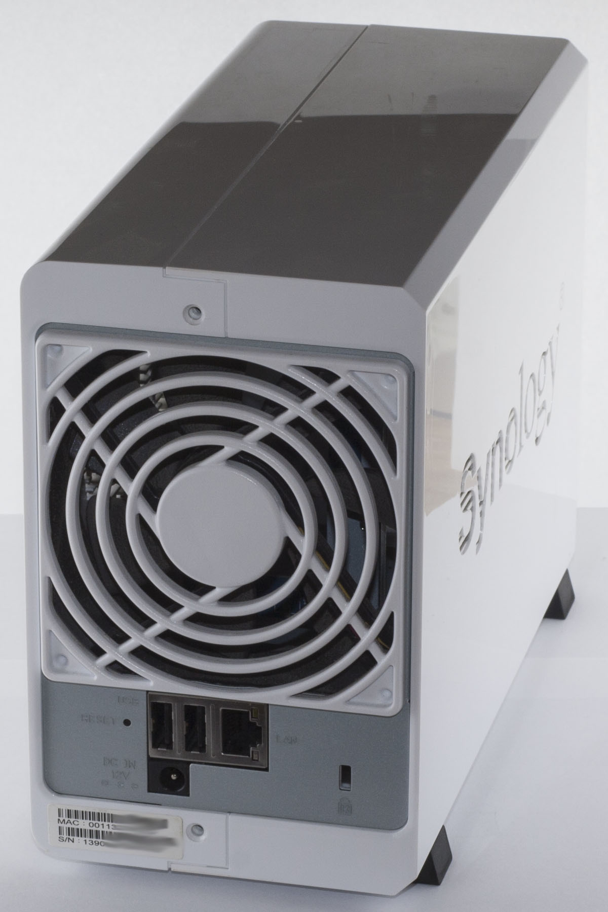
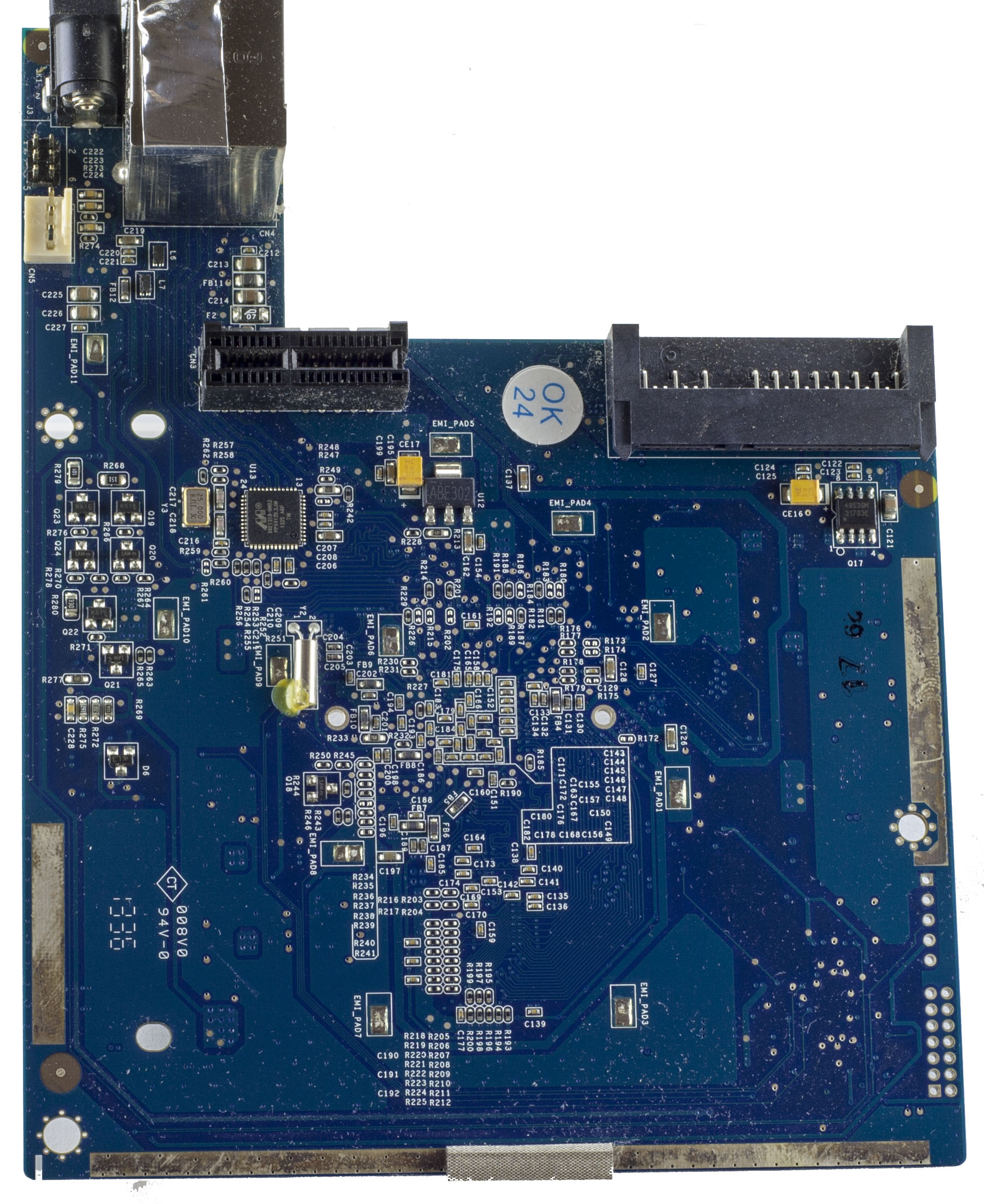
Once inside, we can see there is a backplane PCB for the second hard drive, they are only using the right slot of a PCI-Express x1 connector.
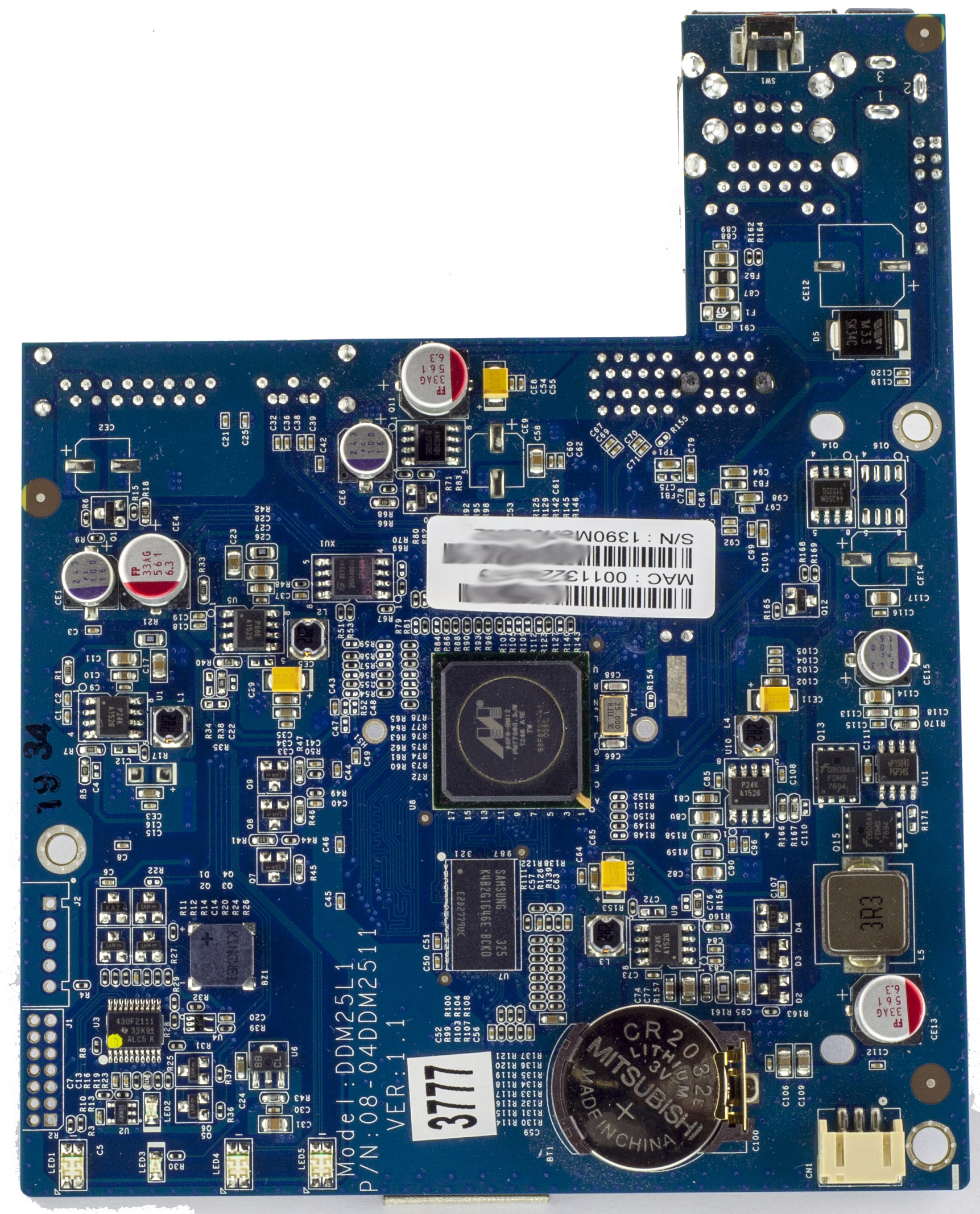
As per the single bay, we’ve got lots of EMI pads (but missing the pads/pins) and some on the PCB edges too. There are 2 unpopulated connectors on the bottom left of the PCB, a 6 pin connector near the power input jack and they have an SMD buzzer on the PCB. PCB date code is 36th week of 2013.
It’s been 5 years since I started making GBCartRead (GB Cart Shield) using the Arduino to read Gameboy ROMs and save games. GB Cart Slots at the time of this post are becoming harder to find (Aliexpress are selling used ones) plus I have some time on my hands so I think it’s time to re-do it without the need of the Arduino. There have been a few users ask if GB Cart Shield supported the Gameboy Advance which it doesn’t, so I will look into supporting that for this new project which I might call – GBxCartRead (the x shows it supports GB/GBC/GBA).
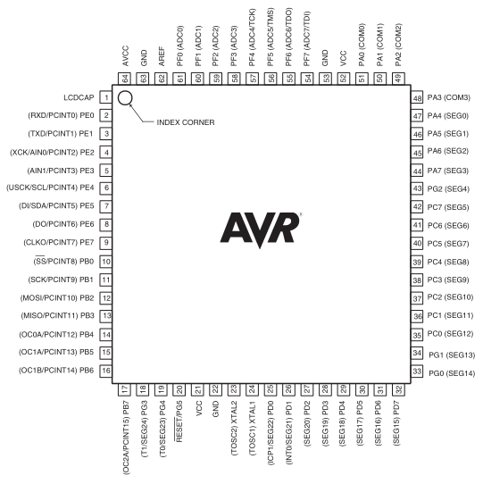
I’d like to remove the shift registers that the GB Cart Shield currently has and look for an AVR MCU which has enough pins to cover the GB slot pins at a reasonable cost. There are few options like the ATmega162, 165, 169.
I choose the ATmega169A for $6 as it came with free shipping from RS and I will be using it for another project, it’s pretty big. It has 54 I/O lines, way more than what we need though it will allow us to use 3 complete PORTs dedicated to the GB I/O.
GBA cartridges are similar to GB carts except that they require 3.3V, use 3.3V logic, have 24 address lines and they switch the first 16 address lines into data lines when reading the ROM. As per the GB carts, you pulse WR low to write, RD low to read and CS low whilst doing either. They have a CS2 line which is dedicated to the SRAM, pulse CS2 low to access it. An upside over GB carts is that we don’t have to do any bank switching for reading the ROM due to the 24 bit address line (32Mbit max) but a downside is that the GBA cart header doesn’t contain any useful information about ROM size, RAM size, etc. There is however a useful gba.xml file from the MAME project (\mame\hash in the source) in which they have documented which cartridges contain what chips.
A while back I made a Small Programmable Power Supply which at first was going to have a P mosfet to control the voltage but I switched to a LM2596 DC-DC when I found the mosfet was getting too hot. The power supply has worked well for me over the past few years but now it’s time to build something better. One of the problems with the old power supply was that when you got to the higher end of the voltage range (6V+), there were big jumps in voltage (0.2V-0.5V) when you turned the knob higher, this is because of the digital pot and resistor divider used to adjust the voltage.
At first I was thinking of doing a 3 output power supply, each output would have their own dedicated DC-DC however upon testing the Richtek DC-DC that I’ve used before with the digital pot, I would still run into the same problem. What we could do is stick a linear regulator after the DC-DC and give it 2-3 volts headroom which would save us from having the linear regulator drop all the voltage on it’s own. I’m currently testing the LM350 which is similar to the LM317 but can handle at least 3 amps and allows for voltages of 1.2V to 33V, I’ll be looking at powering this supply from a 19V power adapter so I could have a voltage range of 1.2V to 15V or so.
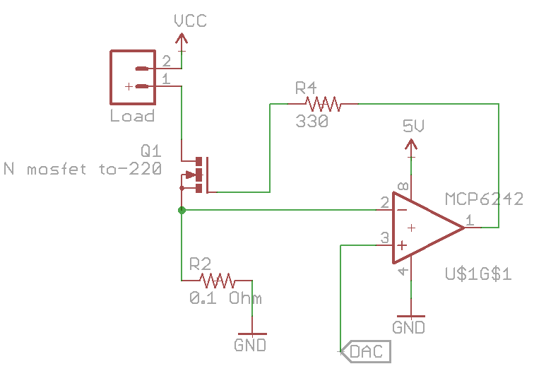
I would also like to add current limiting to the power supply and to see how much current is being drawn by the device under test, I’m looking at either 2 or 3 amps. We can re-use the constant current dummy load circuit and by placing the load before mosfet, the op-amp will regulate how much current will flow through the mosfet. One problem I’ve found is when you hit the current limit, the mosfet is in the linear region just like in the dummy load so it gets really hot. I thought I could get away with a small mosfet without a heatsink but I was wrong, I’ll have to go with a TO-220 style with a decent heatsink. On the other hand, if you did want go with a small mosfet, you could detect that a current limit occurred and then turn off the output.
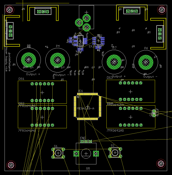
Above is a rough look at what it could look like (10x10cm). I’m looking at having 2x of 4 digit LED displays, one for voltage and one for current, the same rotary encoder like last time and having the power supply be dual output. Two push buttons on either side of the encoder would select the the voltage and then another push for current, the LED display has a little dot light at the bottom right so this could be used to indicate which display was being set or I could add 2 LEDs on either side of the display. No need for shift registers any more as I’d be using an ATmega169A which has enough pins to drive the displays directly.
AdvanceVGA – Play your GBA on the big screen! Swap out the LCD for our board, solder some wires, connect 5V USB and VGA and you’re ready to go.
GBxCart RW allows you to backup GB/GBC/GBA ROMs, save or restore game saves and re-write supported flash carts. Mini RW option available for GB/GBC only.
Wireless Gameboy Controller – Use your Gameboy, mGB, GBC, GBA, GBA SP, GB Micro, NDS and NDS Lite as a wireless controller on Windows, Linux, Raspberry Pi, etc, and on your NES, SNES, N64, Gamecube and Wii.