Posted in Teardowns on Nov 27th, 2016
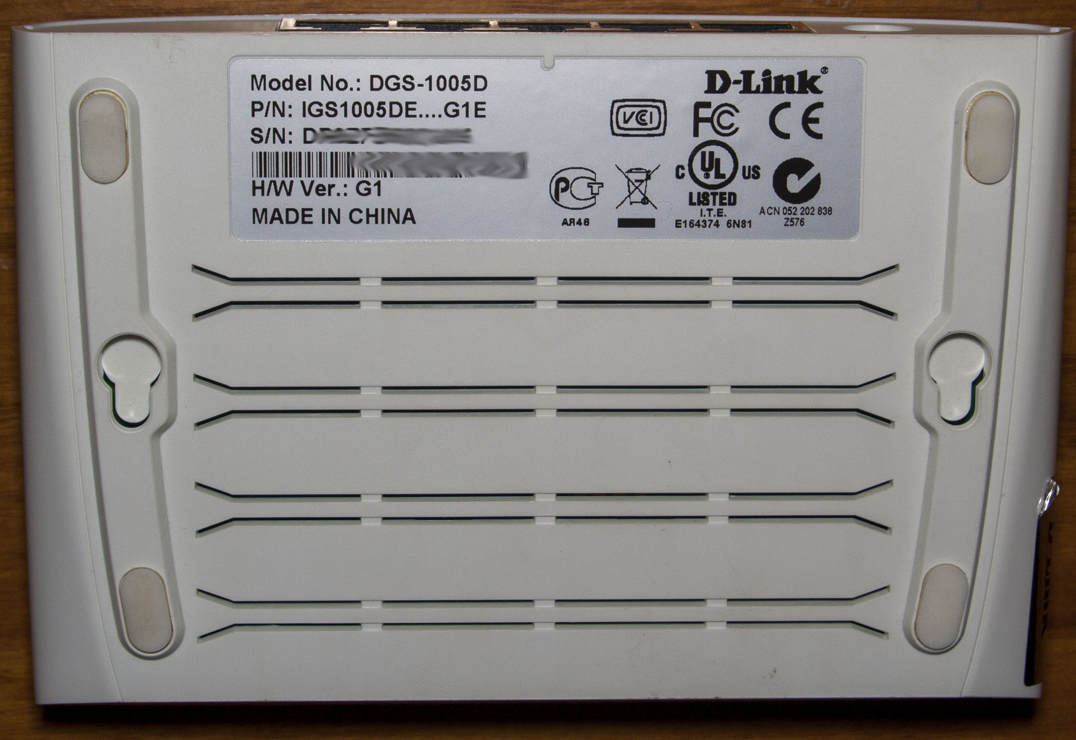
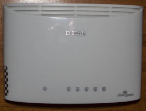
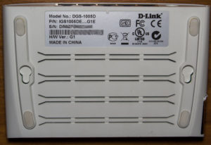
A quick one, today we’ll be taking a look at D-Link 5-Port 10/100/1000 Unmanaged Switch (DGS-1005D) which is a simple 5 port gigabit switch.

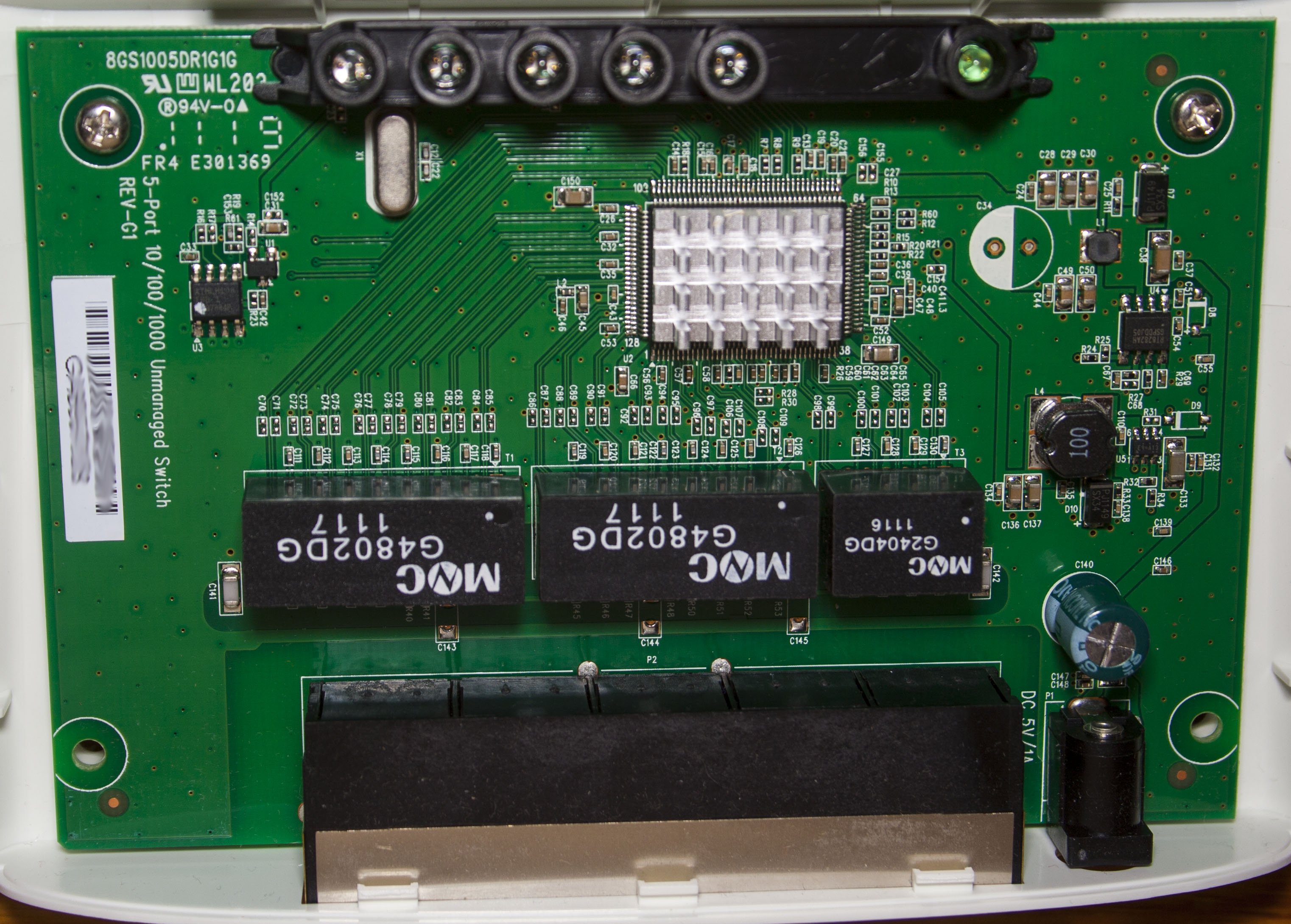
Two screws later and we’re in.
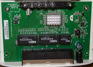
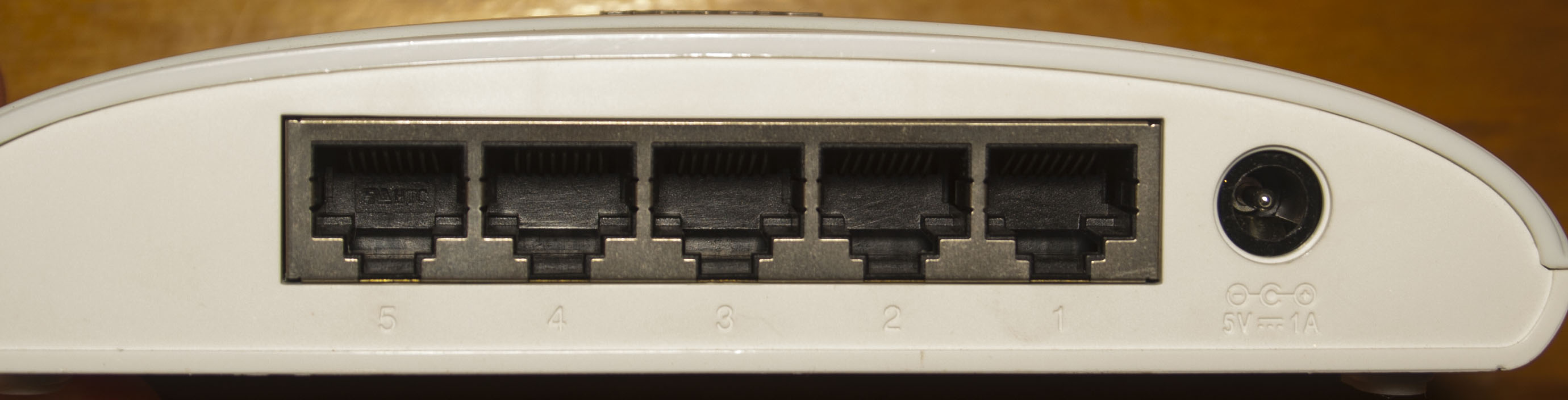
We have 5V/1A input to the switch, a single 470uF electrolic capacitor and two DC-DC converters, a small SOT23-6 (E9=A13) and a Richtek RT8282A (0.8V to 20V output adjustable), good to see this chip in use (as I use a similar one too), but a bit odd that they have a diode on the inductor as it isn’t required with this chip (uses internal switching mosfets), are they looking to reduce the heat on the chip? PCB date code is 19th week, 2011.
(more…)
Read Full Post »
Posted in Projects on Nov 4th, 2016
Its been a while since I last worked on this officially project though I have done a little here and there to gather ideas and testing for the new design. To briefly recap, my first alarm system was on I bought from Ebay and made some modifications to it then I made my own alarm system that has PIR/Door sensors with the NRF24 wifi module.
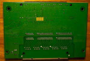
Since my last post on the alarm system, I’ve now removed the 433MHz remote and switched to the Raspberry Pi so I can switch the alarm on/off via Wifi which makes things easy. Also I’ve moved to the SIM900A for SMS sending. It’s been almost 2 years now, I’ve had to charge up of the PIR modules batteries once and most of the door sensors have stopped working properly either because of the coin cell didn’t last, the NRF module or its position so I gave up on them and I’ve had 2 false alarms, one I think the battery was running too low (my voltage cut off may not have been high enough) and not sure about the other one.
Some of my ideas for the new project are:
Use the 433MHz Si4432 module for the wireless network
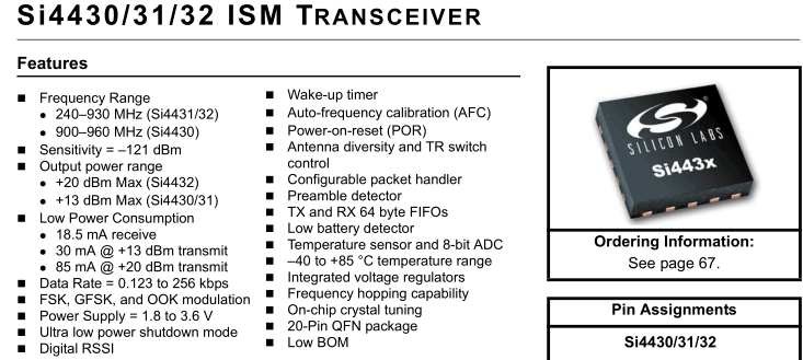
Using this module over the nRF 2.4GHz should allow for better reception in areas that reception was hit and miss, this was in the garage and some spots around the house. Input voltage is 1.8V to 3.6V so it’s quite low. Current consumption is 1uA when sleeping, 18mA in receive and you can change your transmit power from 1dBm to 20dBm (17mA to 85mA), so I might go for 5 or 8dBm which might be around 20mA. The downside is that it’s a lower frequency it will need to be receiving and transmitting for a longer period of time.
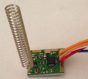
Price is $3 for the module from Ebay so that’s pretty cheap.
(more…)
Read Full Post »
Posted in Teardowns on Oct 25th, 2016
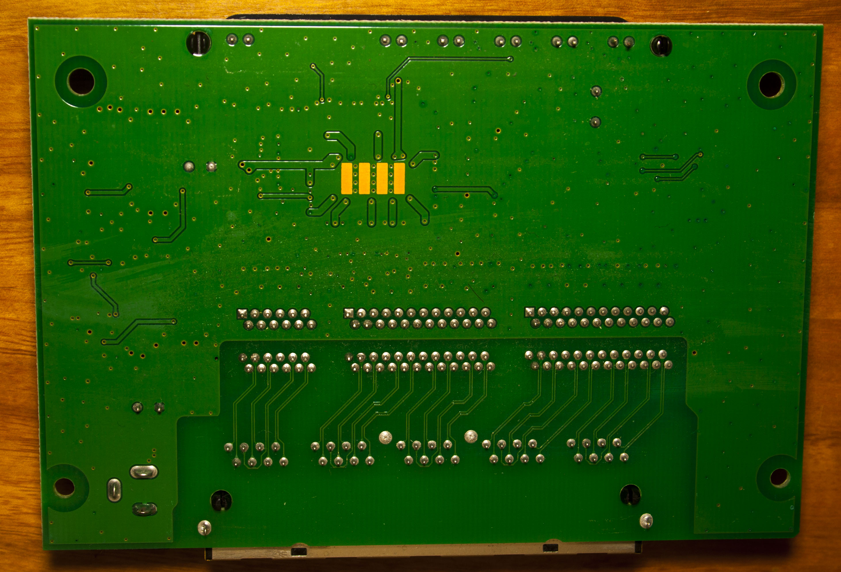
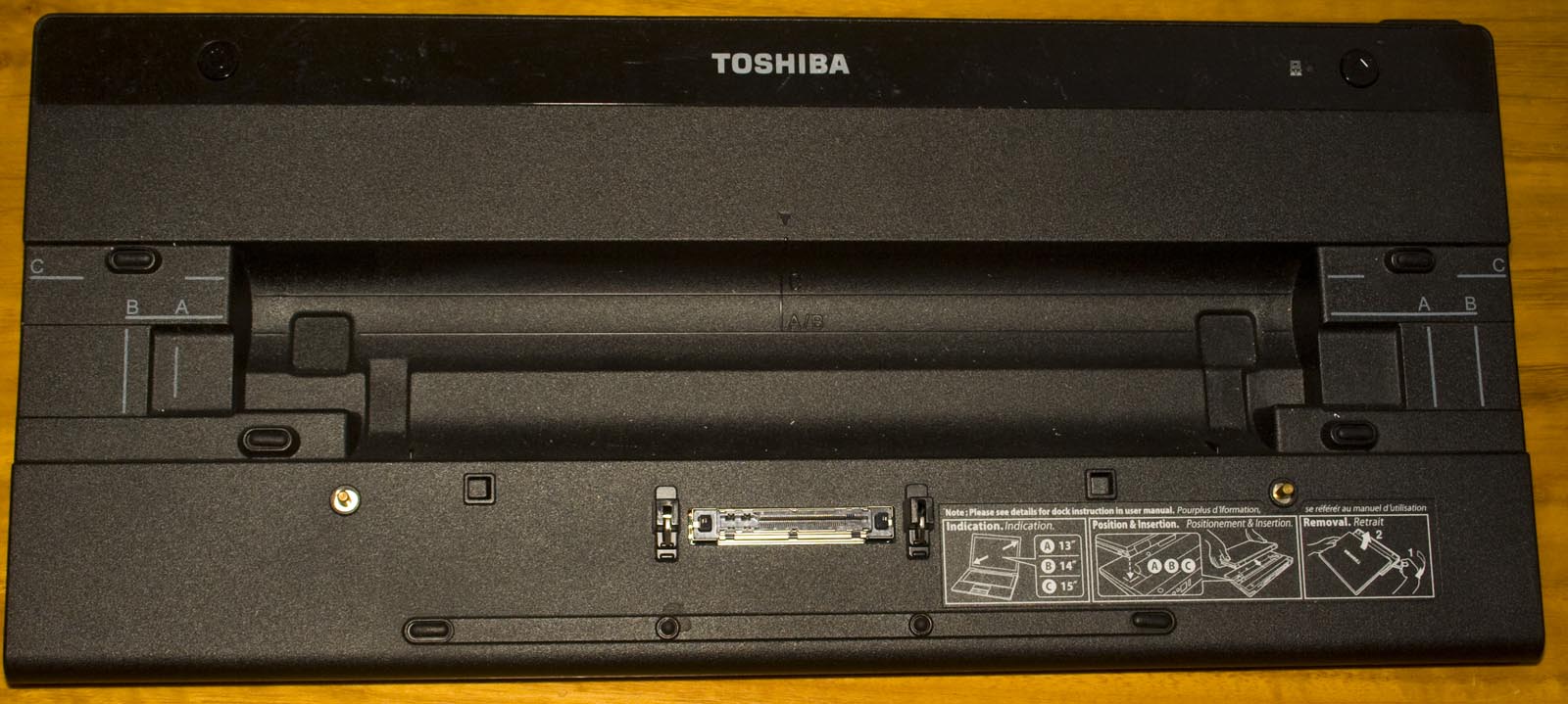
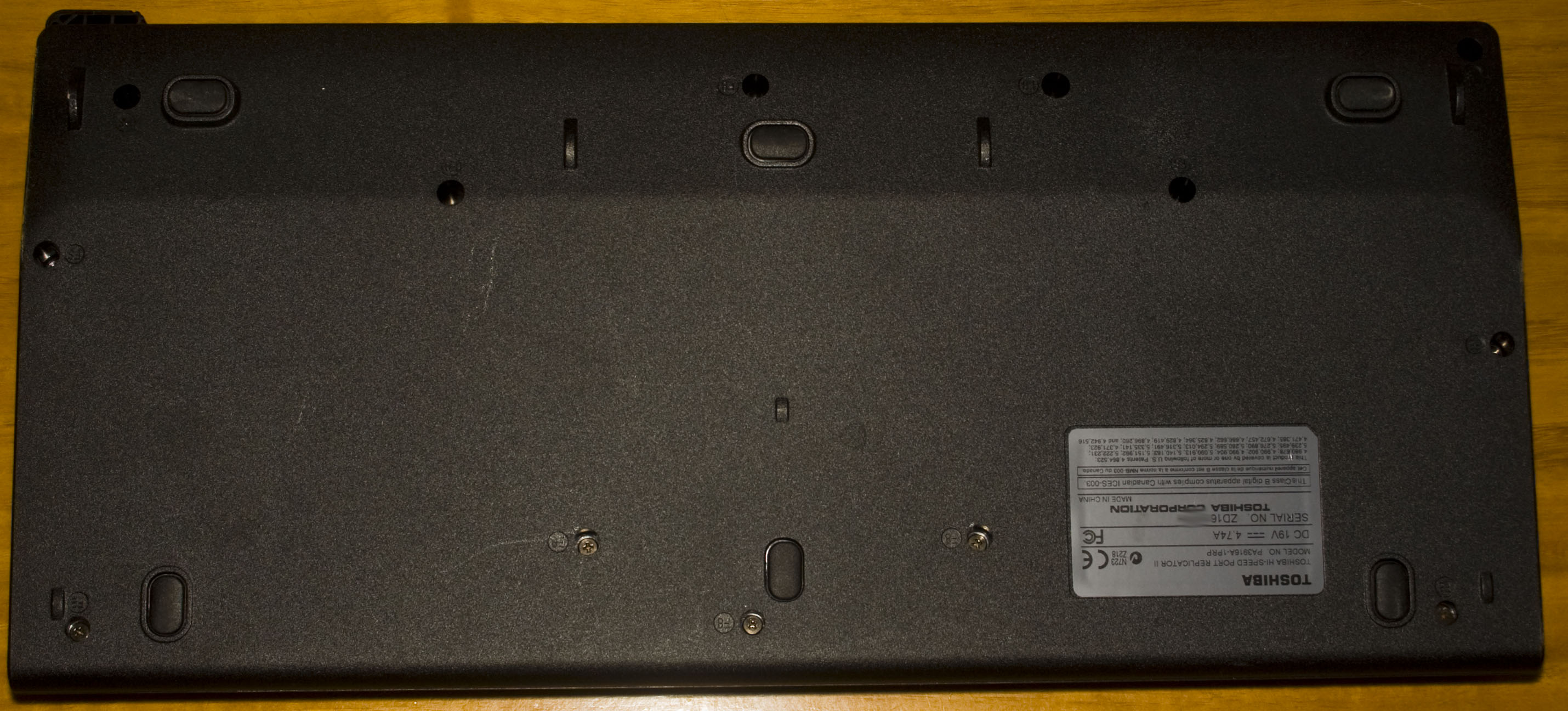
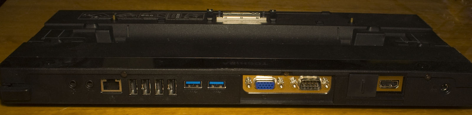
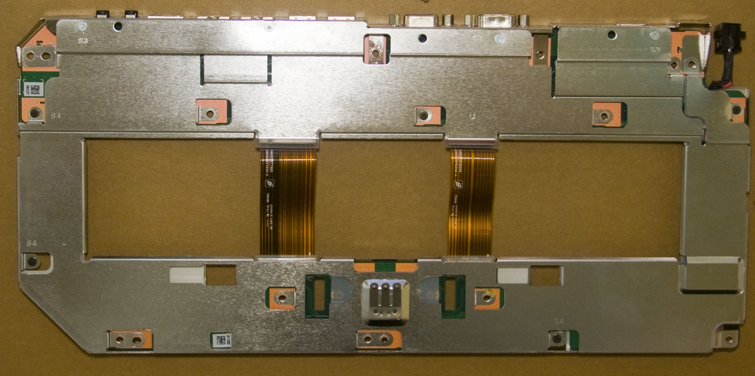
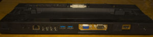
Today we’ll be taking a look at Toshiba Hi-Speed Port Replicator II (PA3916A-1PRP), a docking station for Toshiba laptops which has 2x USB3.0, 4x USB2.0, Gigabit NIC, audio in/out, serial, VGA and HDMI/Displayport.

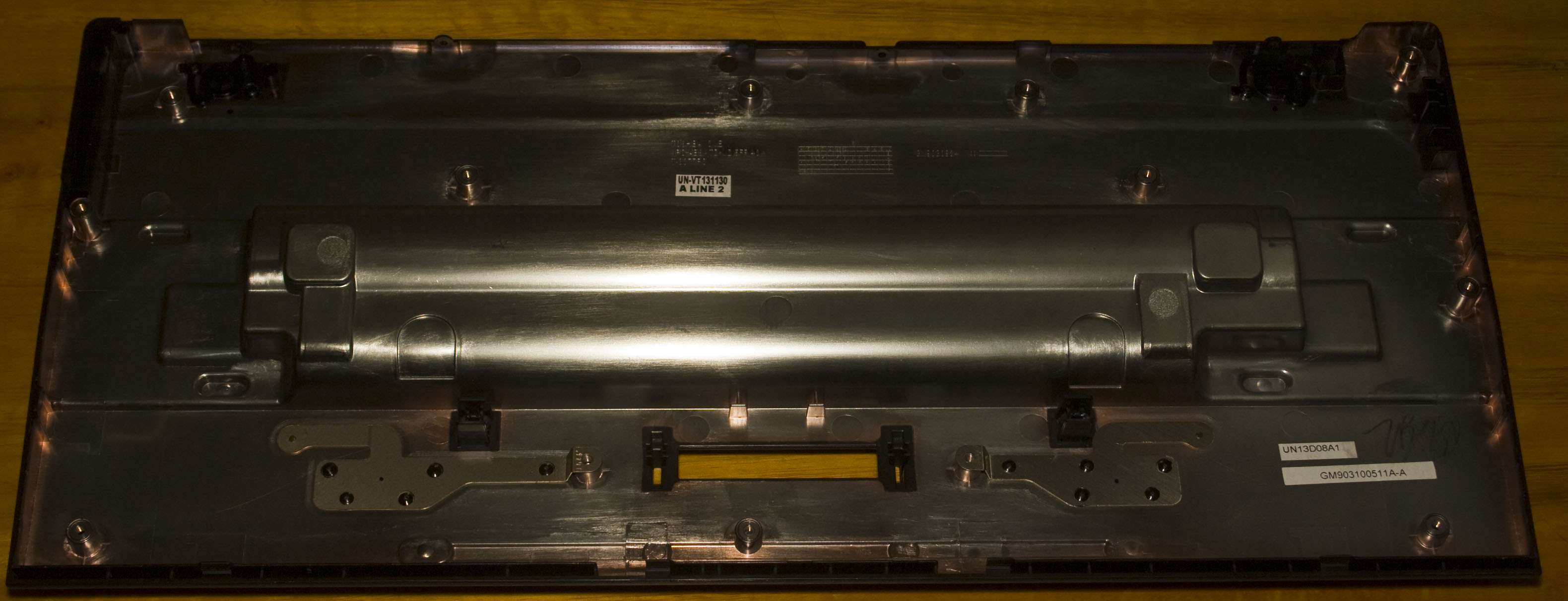
A lot of screws later and we’re in, well sort of.

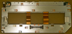
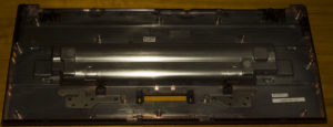

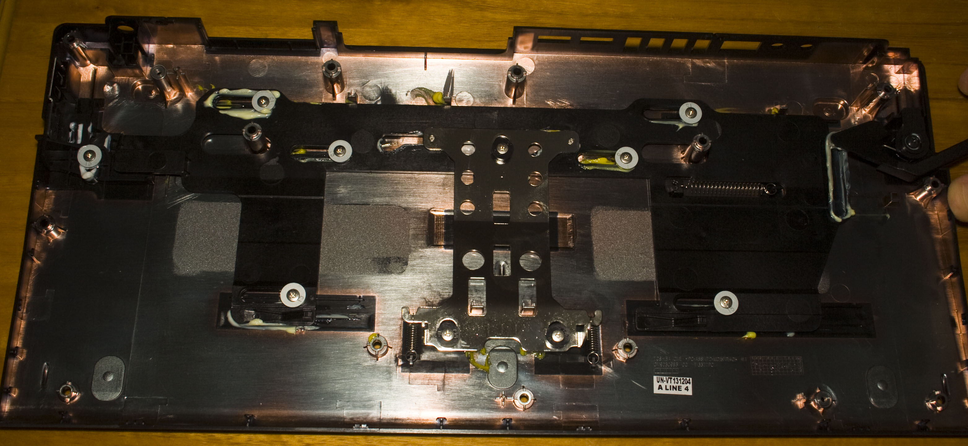
The whole PCB is completely shielded, we have some copper sheets on the outside plastic covers and we can see how the eject lever works.
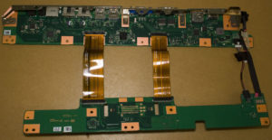

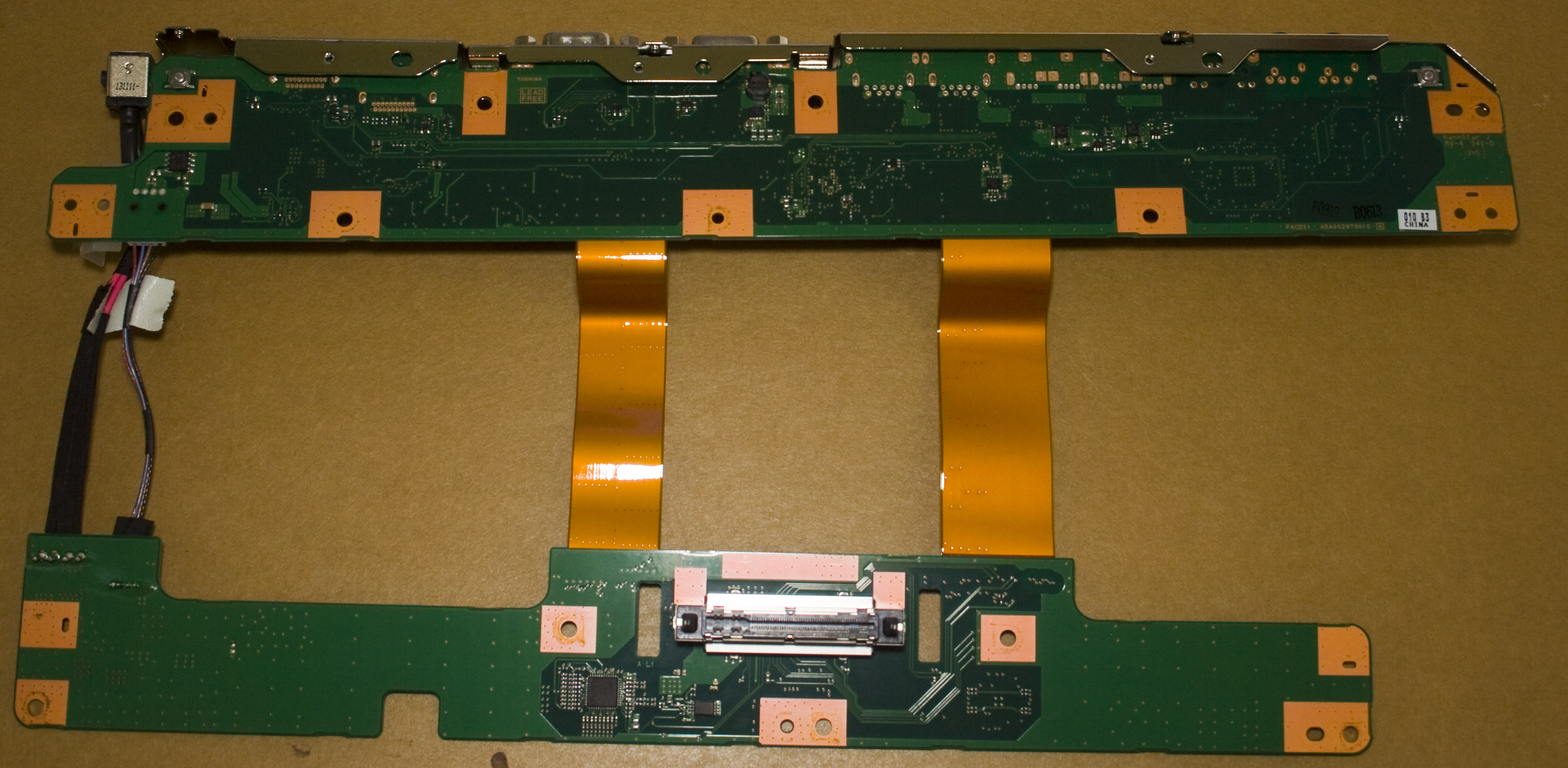
A lot more screws later and we’re really in, it looks nicely laid out. We have the power connector with wires going down to the 2nd board, another power cable coming back to the first board plus 2 flat flex cables. PCB date code is 45th week of 2013.
(more…)
Read Full Post »
Posted in Teardowns on Sep 29th, 2016
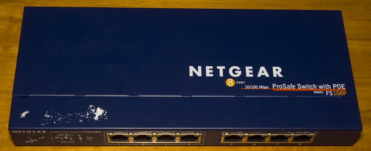
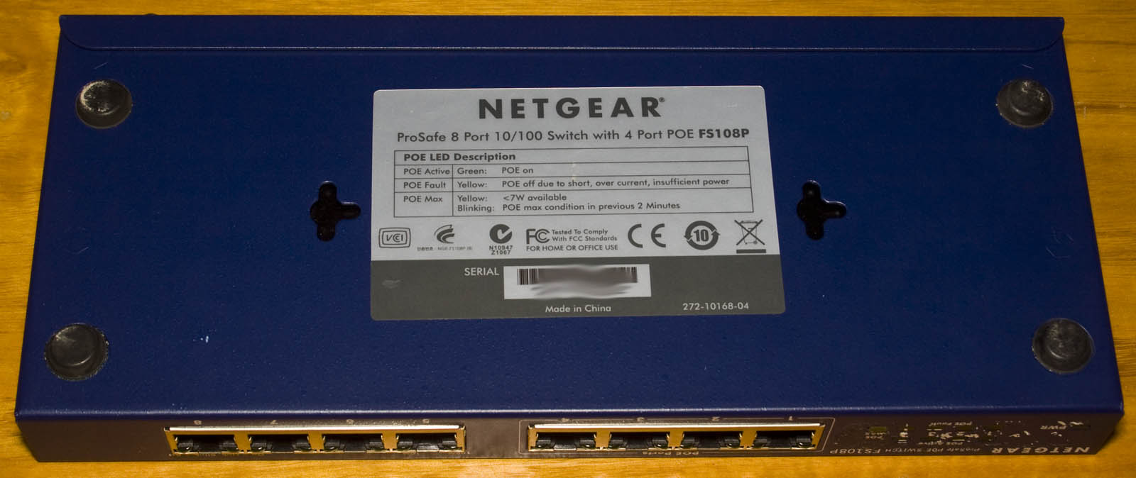
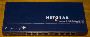
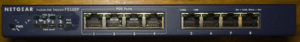
Today we’ll be taking a look at Netgear ProSafe 8 Port 10/100 Switch with 4 Port POE (FS108P) which is an 8 port switch with standard 4x 10/100 ports and 4x 10/100 ports with POE. This would be one of the first POE switches I’ve looked at.

Two screws later and we’re in.
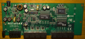
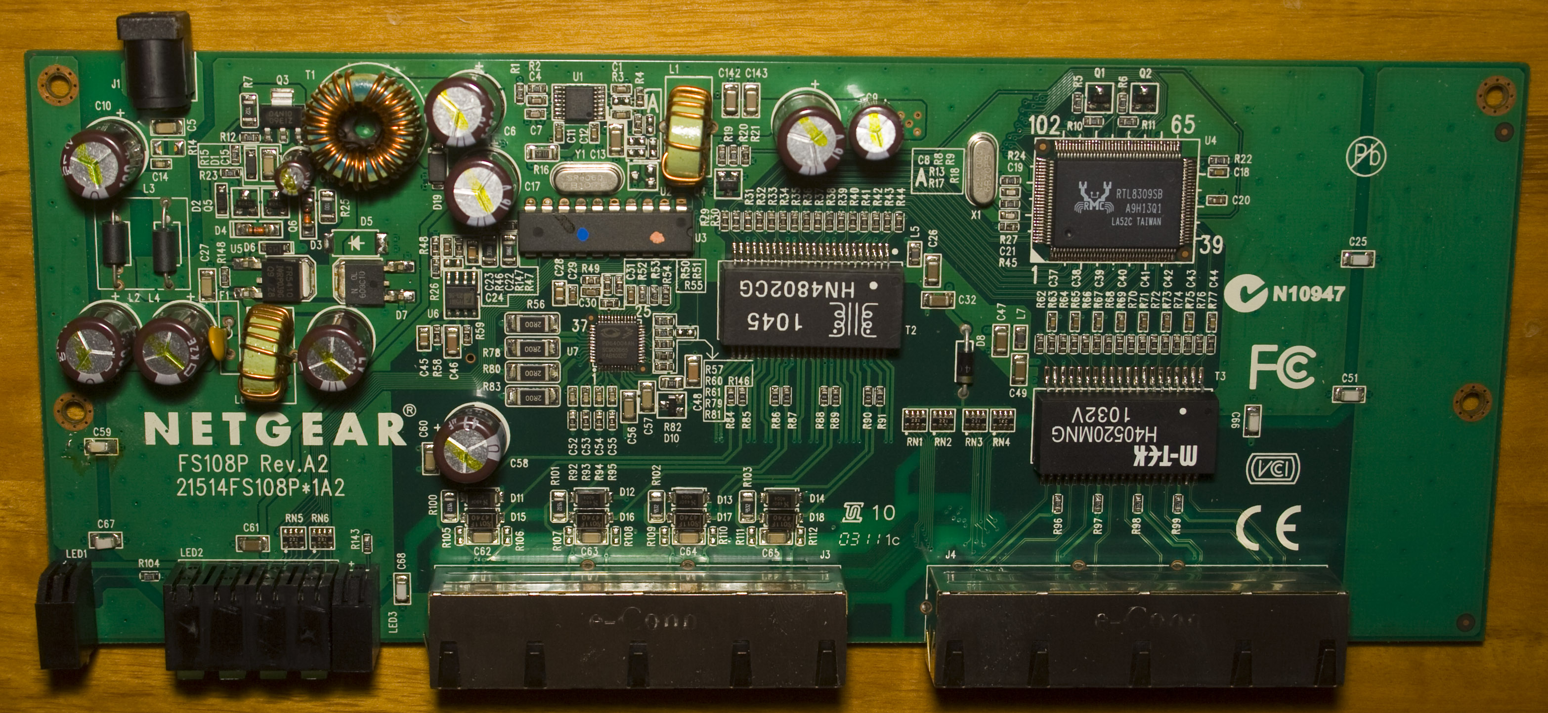
It looks like a pretty standard switch, there is some extra board space to the right of the board so they could have potentially made it smaller (or maybe there is an 8 port POE model which uses that space). Date code is 3rd week in 2011. Some things that pop out are include:
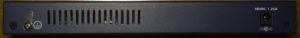
– Instead of being powered by a 12V adapter it’s powered with an 48V adapter so that’s an easy solution to solve the voltage required for the POE ports.
– They use a transformer which looked like an inductor at first but if you take a look closely you will see two separate winding, one thick wire and one thin wire
– They are using a DIP microcontroller, I don’t think I’ve seen a DIP MCU in a switch before.
(more…)
Read Full Post »
Posted in Projects on Sep 11th, 2016
From our last part we added the RTC including programming the time from the PC, some fixes, estimated battery life and briefly looking at some logging results.

I made a quick couple of changes to the PCB and squeezed the voltage logging back in to just have that option available again, briefly tested the new SOT23-5 LDO without issues. A few weeks later and the PCBs turn up, everything looked good and then I built it and found out I forgot to add the I2C resistors and RTC MFP resistor too! A couple of cuts to the board to reveal the tracks and I could solder the resistors and it works.
I started testing the RTC with different capacitors to see how accurate it can be, it seems to work good for a few hours but eventually it started to drift by a couple of seconds after a day which could be due to temperature changes (15C to 25C) over 24 hours or possibly the PCB design. I have a small single sided RTC PCB for my big clock and that used to be 1-2 seconds drift every month which I’ve had for almost a year though now it’s drifting by 3-4 seconds after a few days too, so it is starting to sound like it could be temperature problem thought it doesn’t seem to be as bad; I have had one day where it didn’t drift and then the next day when it did by a lot.
(more…)
Read Full Post »
Posted in Teardowns on Jul 16th, 2016
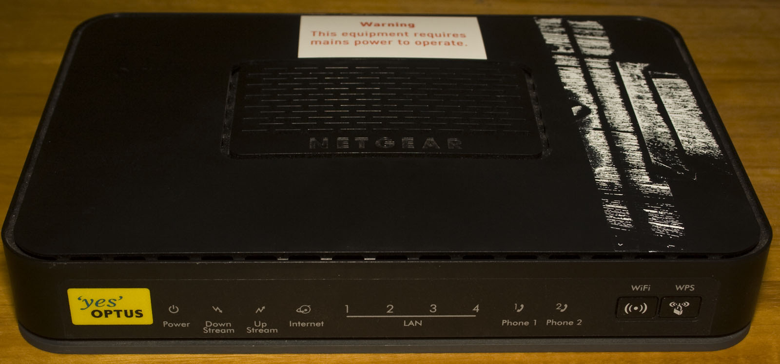
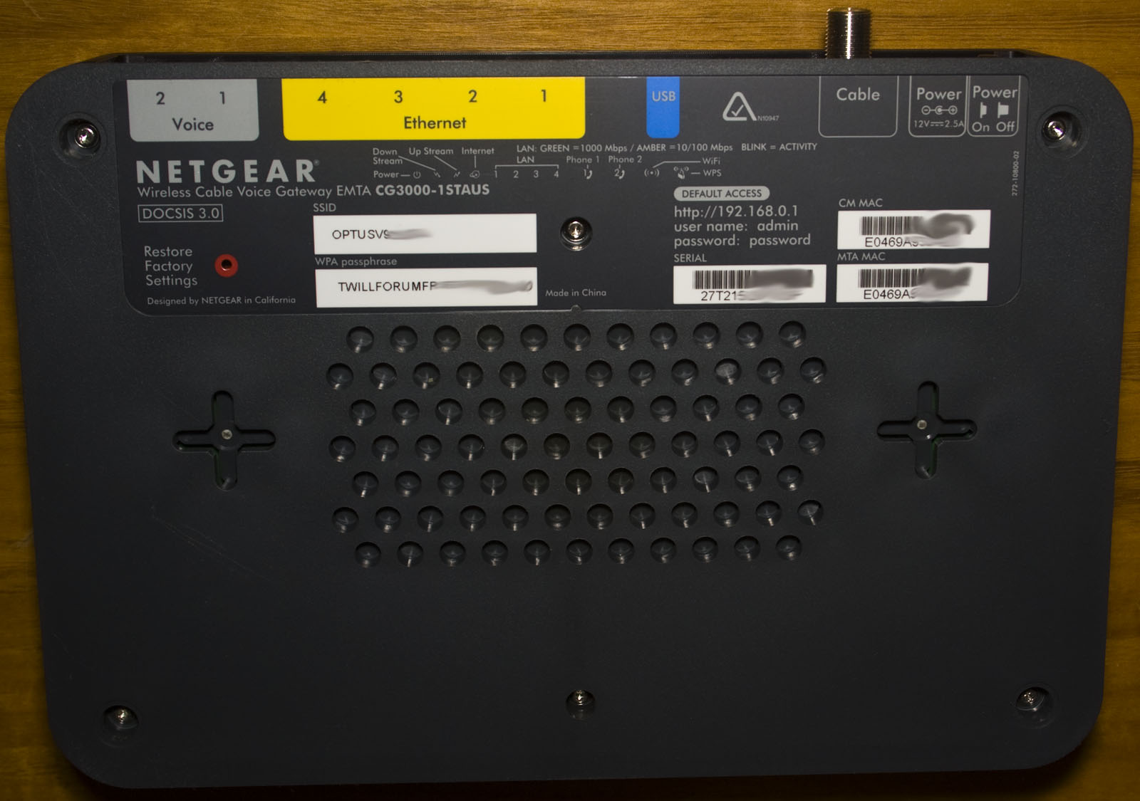
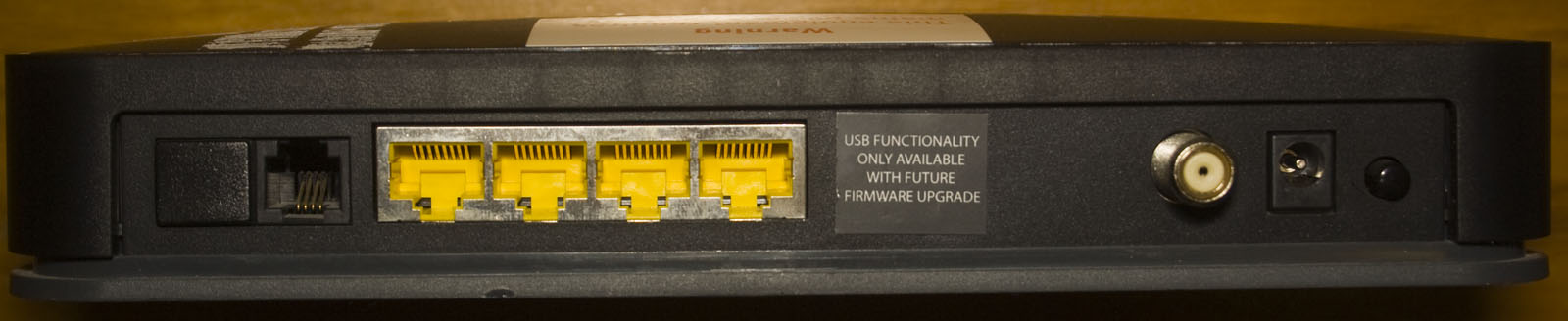
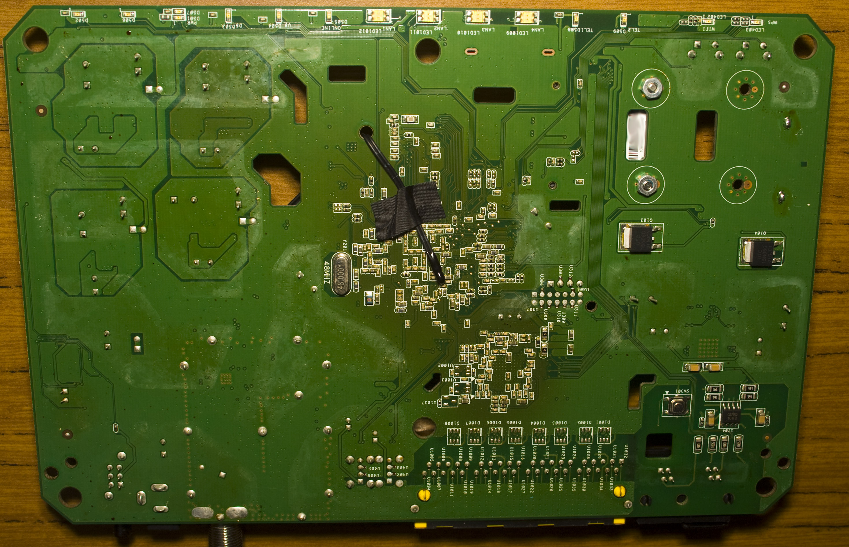
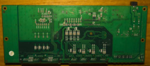
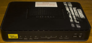
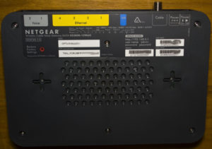
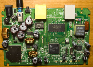
Today we’ll be taking a look at Netgear Wireless Cable Voice Gateway (CG3000-1STAUS) which has 4x 10/100/1000 ports, a USB port, 2x voice ports and a cable coax port. It’s one of the few routers that I’ve teared down which has gigabit network ports and the USB functionality isn’t available according to the sticker placed on top of it so a future firmware may enable it, I guess they had to rush these units out. I’ve changed the teardown format a little bit so it flows a bit better.
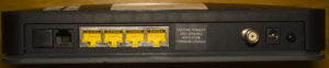
Six torque screws later and we’re in.
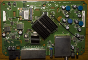

There a few things that stand out from the usual routers I’ve seen, first is the pretty big heatsink on the main chip, we also have a RF can for the cable input and a temperature sensor cable going to the back of the main chip, must get pretty hot. PCB date code is 17th week of 2011.
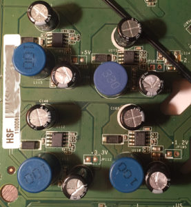
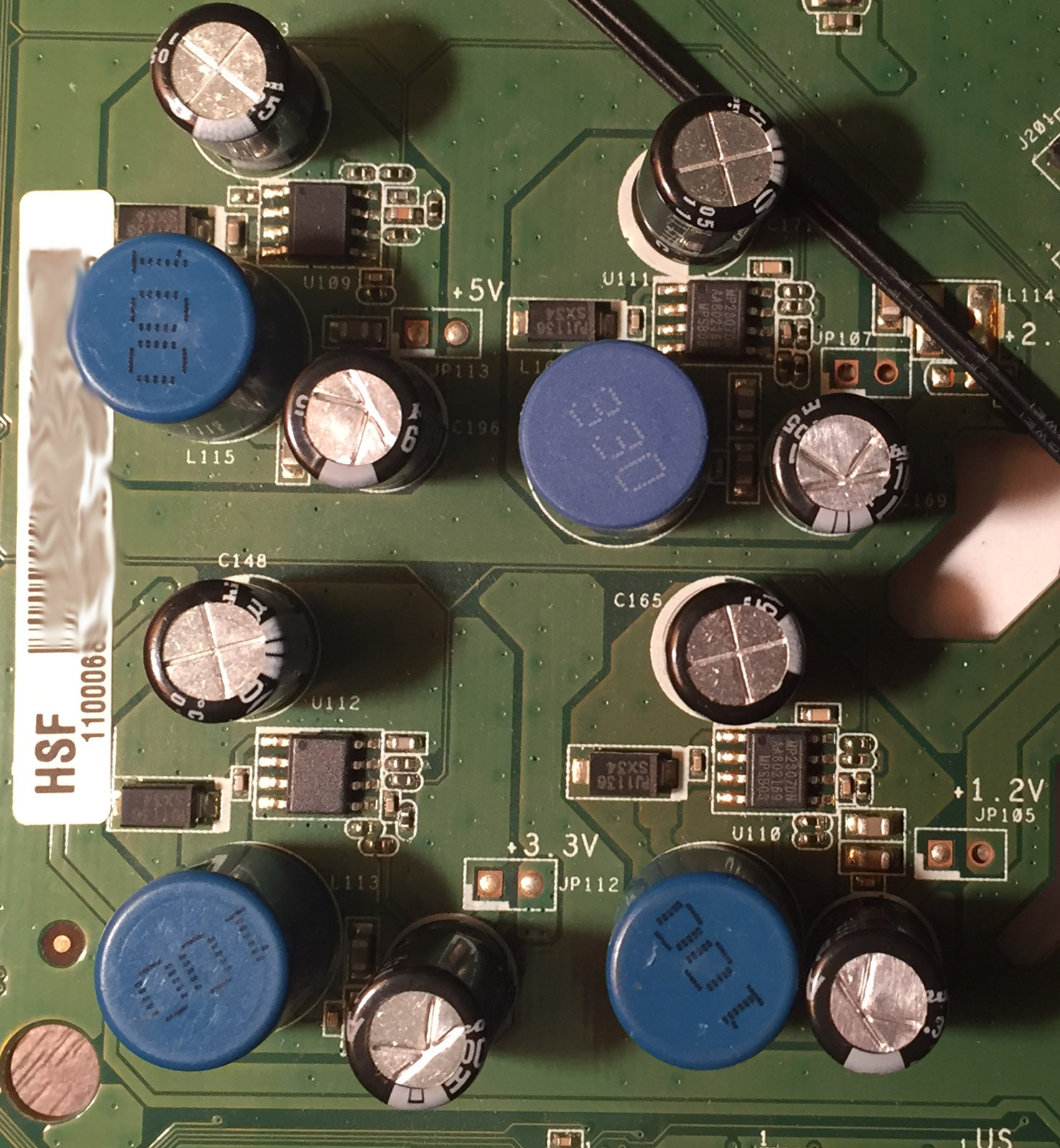
There are 4 DC-DC converters (3x MP2807DN, 1x 71981A/LAB8103) and the inductors look strange, they are in a plastic type package and for the DC-DCs they do have the silkscreen showing the different voltages so that’s nice. Capacitors are a mix of Nichicon and Rubycon for the DC-DCs but they have Lelon ones for the voice lines.
(more…)
Read Full Post »
Posted in Projects on Jun 3rd, 2016
From our last part we looked at adding in the TMP102 sensor, experimenting with I2C pull-ups, re-testing the voltage switcher diode and other improvements/fixes. This time we’ll look at adding in the RTC including programming the time from the PC, more bug fixes, estimating battery life and briefly looking at some logging results.
I started off re-designing the RTC crystal layout which I would also make into a little board to connect up to the breadboard and since I already have a RTC clock project I can use that for reference.
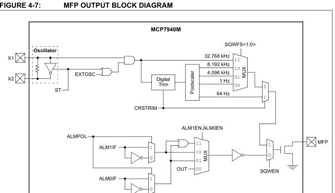
The MCP7940M has the option to output a 1 Hz square wave which is what we’ll use to wake up the ATtiny every second. We no longer need to use the watchdog timer which takes about 4uA when in use where as the RTC takes 1.2uA.
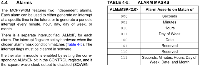
An alternative is to use the alarm capability build into the RTC to wake us up however this would mean that for 1 second logging, you would need to constantly reconfigure the alarm for the next second which could be complicated in the end and you might spend even more current reconfiguring it however for longer logging delays say every minute or hour it would make sense but I’ve opted to keep everything simple for the moment and just use the 1Hz output.
(more…)
Read Full Post »
Posted in Teardowns on May 11th, 2016
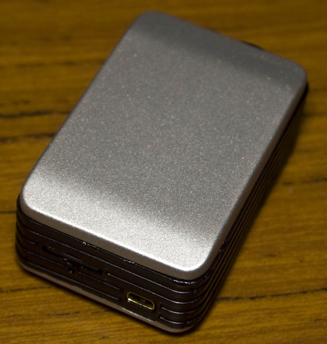
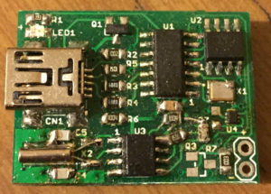
Today we’ll be taking a look at a low cost Action Cam, the VWTech VW898 ActionCam which does 1080p @ 30fps, 720p @ 60fps with a 135 degree wide angle lens cost me $35 AUD from Ebay which is about half the price of a Mobius ActionCam. I decided to buy this after my Turnigy camera stopped recording audio, the price was good and if the quality wasn’t good I could use this camera for something else.
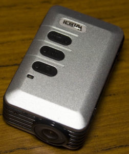
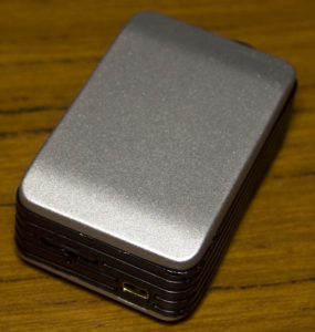
This camera is quite heavy, mostly it’s the 2 outer shells which combined weighs 33 grams. Once we pop those out, the camera weighs 31 grams. The shell not only protects the device but has some foam to keep the camera in place otherwise it can move a little bit. I do prefer the Turnigy’s 185 degree lens over the 135 degree lens and you have to boost the audio up quite a lot in post processing but anyway, on to the teardown.

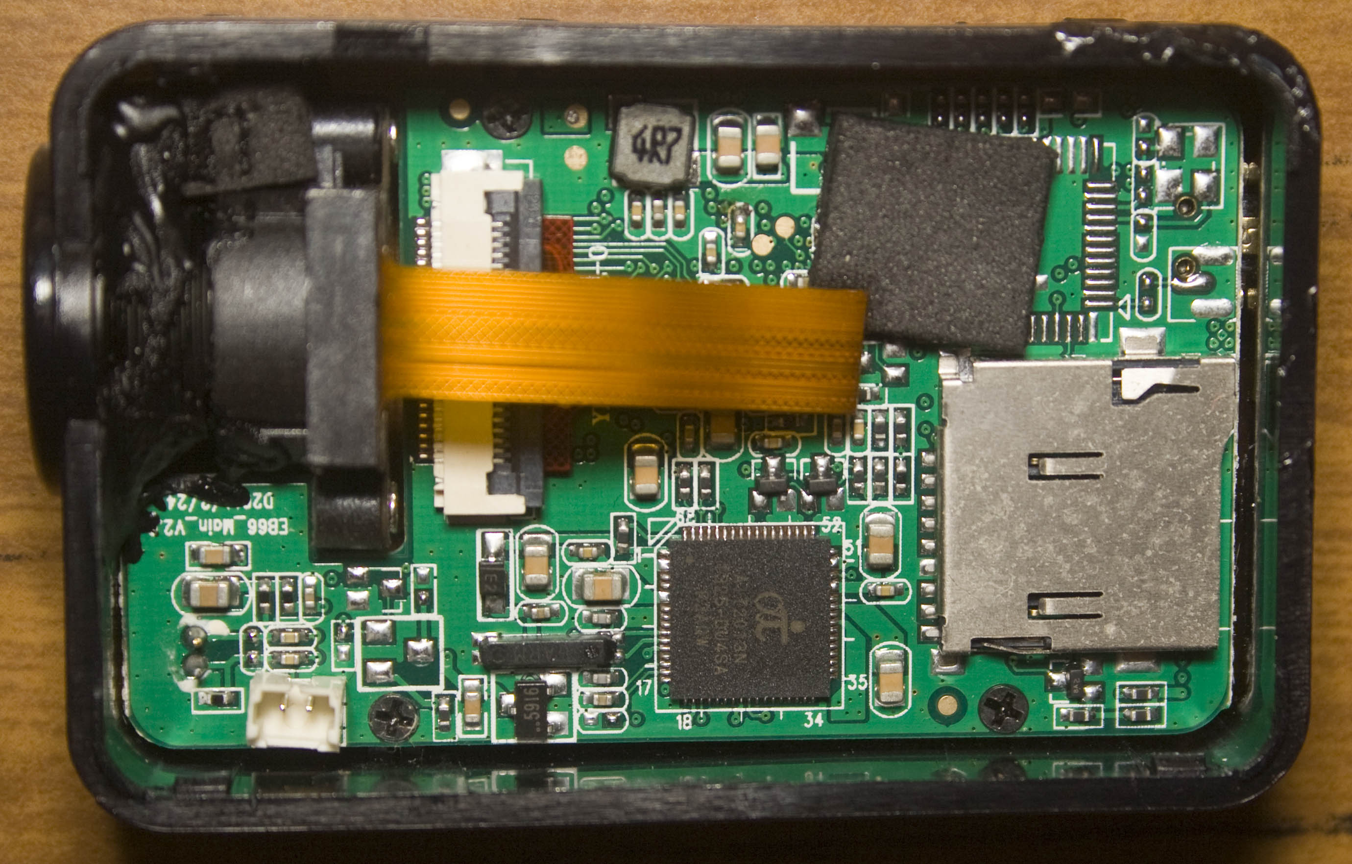
The build quality is ok for this cheap camera, it’s a 3 chip solution and we have 3 small SOT23-5 DC-DC converters and the camera is glued in place; apart from that there isn’t a whole lot to see.
(more…)
Read Full Post »
Posted in Teardowns on Apr 20th, 2016
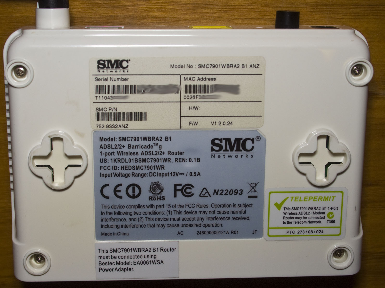
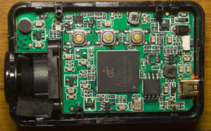
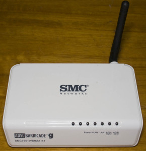
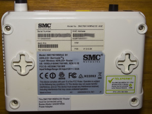
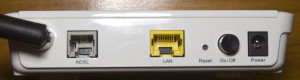
Today we’ll be taking a look at a router, the SMC Networks ADSL2/2+ Barricade G Wireless Modem/Router (SMC7901WBEA2 B1) which is a 1 LAN Port Wireless ADSL2Modem/Router in a small form factor compared to other routers but that’s mostly due to it having only 1 LAN port.
Four screws later, the top pops out and we’re in.

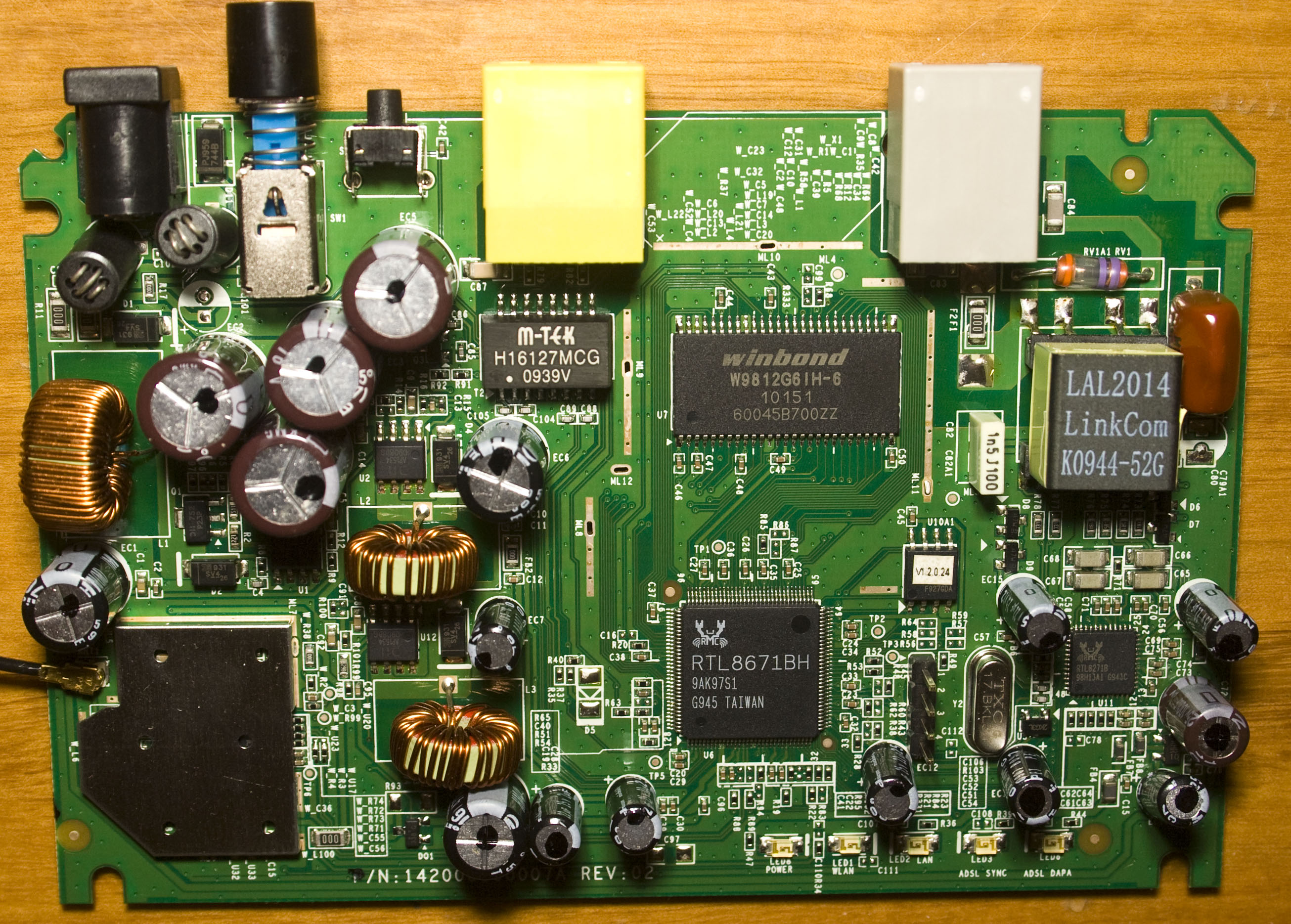
We’ve got 3 main chips plus the Wifi chip shielded with a fair bit of capacitors, 4x 16V 1000uF KMG branded caps near the input and we have 2x AP1534 and 1x AP34063 DC-DC converters, the inductors aren’t glued down at all. Interestingly there may have been the possibility to shield the SDRAM and one side of the SoC too, I guess it wasn’t needed. We have a u.FL connector going to the antenna. PCB date code is 46th week of 2009.
(more…)
Read Full Post »
Posted in Projects on Apr 3rd, 2016
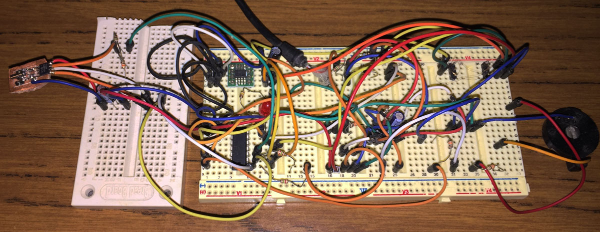
I’ve had the HobbyKing Rattler for some time now and I’ve been making small modifications here and there which have accumulated over time and has gotten to the point where it would be nice to have everything on a custom PCB.
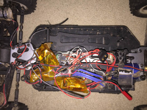

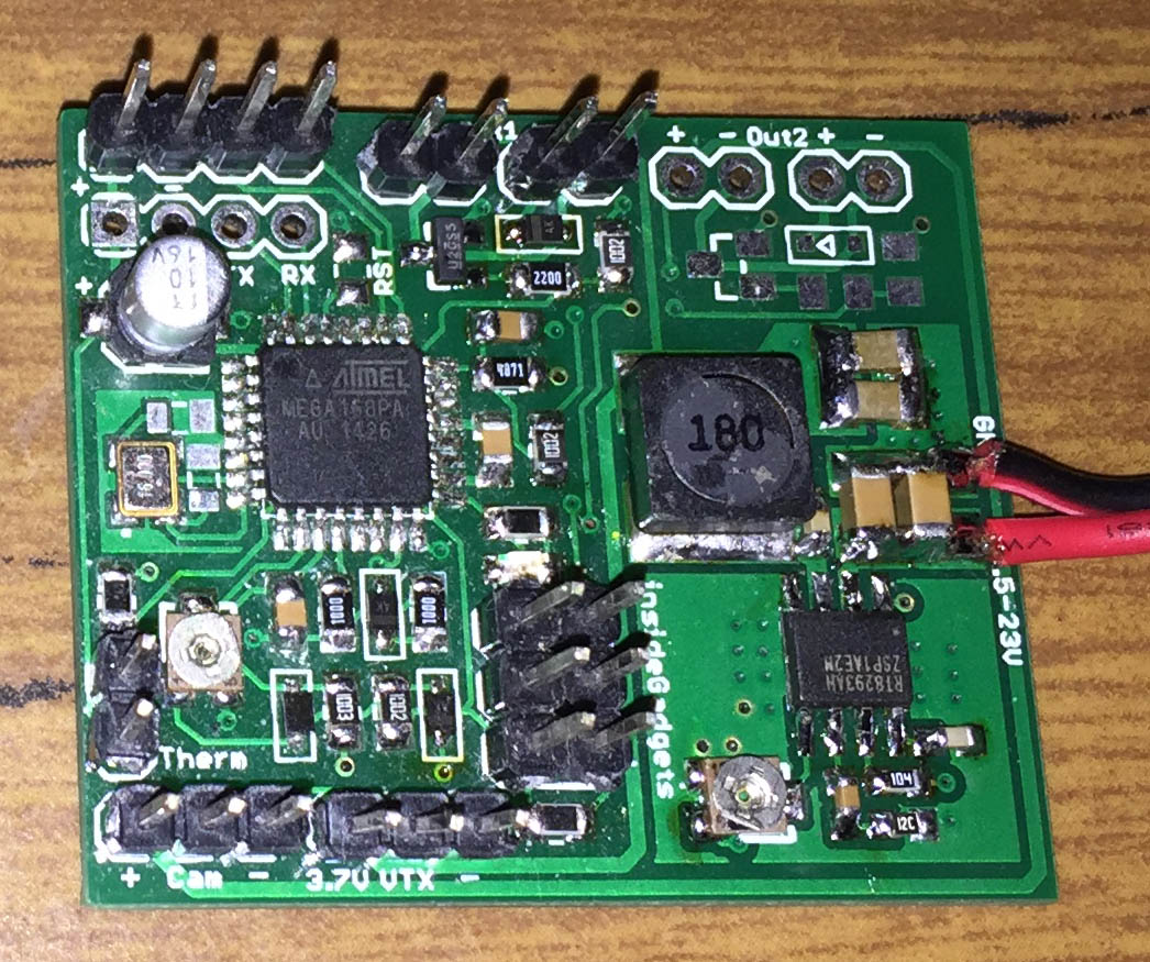
Here’s how everything looks at the moment, pretty messy with kapton tape wrapped around each separate board, we have a large DC-DC converter bought off Ebay a while back for the video transmitter (VTX), an ATtiny control board for the lights/connecting to the receiver and an ATmega with another board doing the temperature/video osd. On the right, we have the finialised PCB.
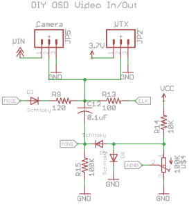
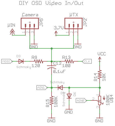
Let’s start off with the video OSD as it’s what the whole board revolves around, I’m using DIY OSD which uses an ATmega with some resistors, diodes and capacitors to overlay text over the screen and it works fairly well. It’s written in Arduino so I’m going to have to use that and I took out the GPS code references so we can fit it into an ATmega168. There are other solutions like Minimosd use a dedicated chip (MAX7456) to do the overlay and the text it generates is better however I wanted to keep things simple and small.
(more…)
Read Full Post »