I’ve been playing around with the idea of rebuilding the temperature loggers I’ve done in the past (SATVL / A25TTL); both have their advantages and disadvantages. I’m looking at going a little bit larger than the A25TTL so it would have a proper SMD battery holder, combine the logger and reader into one again like the SATVL and look at having an option to use the TMP102 temperature sensor (0.5C accuracy), upgrading the EEPROM to 1Mbit and possibly look into adding a RTC later on.
Recombining the logger and reader into one means the ATtiny13/25 that I’m using won’t do the job so an ATtiny44/84 or ATtiny841 should have enough pins however if we do go with the TMP102 its supply voltage is 1.4 to 3.6V which means we’ll need to use an 3.3V LDO or similar when connecting up to the USB. With 3.3V to the MCU we’re limited to a 12 MHz which is just enough to run V-USB.
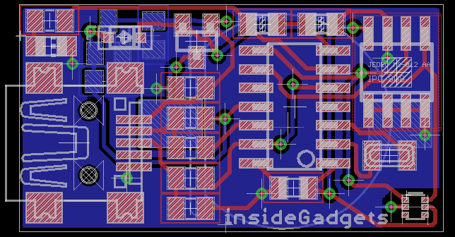
I did a quick mock up of how the PCB could look like (29×15.5mm). To keep the PCB as small as possible, I’ll be using all SMD parts and going with a SOT23 LDO (Richtek RT9166) and a small 12MHz crystal (3.2 x 2.5mm). The MCU will still be using the watchdog timer (for the time being) when it’s doing the delay time so the accuracy is still going to be around 10% -/+. I’ll have the battery holder on the back like the SATVL does and the TMP102 (which is smaller than I expected) on the bottom right without the ground plane near it to reduce any effect it might have on the temperature reading.
Re-designing the voltage switching circuit
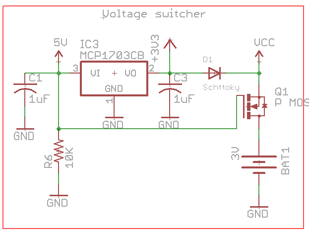
With the SATVL the voltage switching circuit relied upon there being two different grounds for the 3V and 5V. Now I’ve changed it to be a bit more simple and was able to reduce the circuit to 3 components (mosfet, diode and resistor). As with previous circuit the P mosfet only turns off when the 5V USB is connected, there will be a small voltage drop after the diode which I measured to be 182mV drop at 4.5mA so it’s not too bad.
Detecting USB connect / disconnect
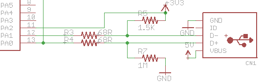
To detect whether the USB was plugged in, I used to check the USB D- pin, increase the clock speed and start the USB however I didn’t really have any way to see if the USB communication ended. We could put an interrupt on the D- pin and check it over time however that could impact the timing on V-USB.
startUSB();
while (1) {
	usbPoll();
	PORTA |= (1<<ledThermistorPin);

	// Check if USB was disconnected
	if (!(PINA & (1<<usbSensePin))) {
		break;
	}
}
Now that we’ve got pins to spare, I can hook up a pin connecting on the LDO’s output so once that goes low we know that the USB has been disconnected. Once it’s disconnected, we’ll just sleep forever until the battery removed and reconnected otherwise the logging will begin again – I might think about adding a small tactile button for this instead if I have a bit more board space.
ISR(PCINT0_vect) {
	// Disable pin change interrupt on 3.3V sense pin
	cbi(GIMSK, PCIE0);
	cbi(PCMSK0, PCINT1);

	_delay_ms(5);
	if (PINA & (1<<usbSensePin)) {
		watchdog_reset_16ms();
	}
}
Once we are in our data logging routine and the USB is plugged in, the pin change interrupt will trigger and if the 3.3V LDO pin is high, then we’ll just reset the MCU through the watchdog and it will eventually reach the USB communication procedure.
Updating Thermistor function / Delay time transfer
Temp = 1 / (0.001138942 + (0.000232762 + (0.000000091 * Temp * Temp )) * Temp);
Ever since I moved the thermistor function over to the PC side, I should have changed the thermistor function to suit.
double tempBetaB = 3455;
double tempAmbient = 25 + 273.15;

double tempLog = log((double) (10000 / ((10240000/(double) RawADC) - 10000)));
double tempCalc = tempBetaB / tempLog;
double tempResult = (tempCalc * tempAmbient / (tempCalc - tempAmbient)) - 273.15;
if (tempLog == 0) { // Natural log of 1 is 0 which means it's 25C
	tempResult = 25;
}
Now we longer have to pre-calculate any variables like we did before (to save flash memory) and it’s easier to change depending on your thermistor.
else if (rq->bRequest == USB_DELAYTIMESEND) { // Transfer delay time and reset data count
	dataCount = 0;

	nextDigit = &replyBuf[-1];
	*++nextDigit = soft_i2c_eeprom_read_byte(EEPROM_ADDR, delayTimelocation); // Seconds
	*++nextDigit = soft_i2c_eeprom_read_byte(EEPROM_ADDR, delayTimelocation+1); // Minutes
	*++nextDigit = soft_i2c_eeprom_read_byte(EEPROM_ADDR, delayTimelocation+2); // Hours
	*++nextDigit = soft_i2c_eeprom_read_byte(EEPROM_ADDR, delayTimelocation+3); // Days

	*++nextDigit = '\0';
	usbMsgPtr = replyBuf;
	return sizeof(replyBuf);
}
I’ve decided it’s worth moving the delay time transfer to it’s own USB request, so that we no longer need to extract it from the real data at the start of the transfer.
Re-visiting EEPROM writing method
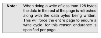
Before for each time data was logged, I used to write 4 bytes – the 10 bit value in 2 bytes and the 2 bytes stop bits which indicates the end of the data logging. I was re-reading the EEPROM datasheet and it turns out that for each byte write that occurs, it re-writes the whole page so potentially for a 128 byte page, we would write 512 times (128 x 4) which is quite a lot and would only give us 1,900 or so times we could start the data logging process.
We have a few options –
- Write the 4 bytes in a page write and have it automatically refresh the whole page – we’d now get 7,800 times we could start logging
- Store the logged data in SRAM then write the whole 128 byte page at once – we’d have the theoretical 1M times
- As far as I know the ATtiny’s internal EEPROM can write each byte and doesn’t need the page refreshed so write the logged data into the ATtiny’s EEPROM and then transfer it into the external EEPROM in a single page write. We’d need to make sure we don’t exceed the 100K writes the ATtiny’s EEPROM has.
The 3rd option looks promising but means that we’d need to wait about 4 ms for each write which is sort of what we do now but offers the best data protection though I may actually go with the 2nd option with a small tweak – re-write the page every 32 bytes (so 4 writes per page, 250K times) until it’s filled just in case something goes wrong, for example, if the battery is disconnected when logging, we won’t lose all 128 bytes waiting to be written. The 2nd option will require a button so we can indicate when the logging is finished and then we can write the final data to the page. By storing the data in SRAM and only writing to the EEPROM every now and then, we’re going to increase our battery life quite a bit.
In the next part we’ll look at the new code for writing to the EEPROM, check our I2C timings to ensure we keep things up to spec and maybe even save more battery life, upgrade the EEPROM to 1 MBit and look at our capacitor requirements for the LDO / test our capacitors.
Building the Mini Temp Logger Part 1: Re-design of the SATVL/A25TTL into another product
Building the Mini Temp Logger Part 2: LDO capacitors checks, testing I2C timings and using EEPROM page writes
Building the Mini Temp Logger Part 3: Using the TMP102 sensor, testing I2C methods and other small improvements
Building the Mini Temp Logger Part 4: Adding RTC and Estimating battery life
Building the Mini Temp Logger Part 5: PCBs arrived and RTC Testing
Building the Mini Temp Logger Part 6: RTC Auto Trim & Voltage reading
Mini Temp Logger v1.0 Released


Hello,
I made a Teeny 3.1 based reflow controller – see https://www.youtube.com/watch?v=TV1dzve0Tck and I can get easily Serial print from Arduino to miniSD card.
I came across your web surching for possibility to get a temp. printout to computer without using Arduino as serial receiver …. adding a USB or similar ?
What would be your recommendation ?
Thanks,
Mike
Hi Mike,
I would recommend using V-USB with an ATtiny45/85 or similar, it’s a simple circuit and there is a good tutorial here about it: http://codeandlife.com/2012/01/22/avr-attiny-usb-tutorial-part-1/
Please contact me at mike.menci@gmail.com
Thanks