An idea came to me after looking at some Gameboy projects which swapped out the Gameboy PCB for their own custom board – What if we could use any Gameboy (GB, GBC, GBP, GBA, GBA SP) as a game controller, stream that over a wireless connection and use a V-USB to act as a HID keyboard or joystick. It’s now available for purchase at www.wirelessgbc.com.
It’s do-able I thought, I’ve already played around with all parts that would make this project, I just have to put it all together (and have some code I can re-use): GBDK to make the rom, either a CPLD or MCU to read the input/data, nRF24L01 or similar for the wireless and V-USB on an Atmel MCU for the joystick input. I was considering using Bluetooth as well but might as well just stick with what I know for the moment.
V-USB Joystick Interface
At first I thought about using V-USB just to output keystrokes as I had done this before with the SATVL however I quickly found that outputting and repeating a keystroke like the right cursor key, doesn’t replicate well into an emulator. Basically it’s just like the key is being pressed and released quickly, so if you wanted to move your player right, it would move them right for a little bit, then stop, move right more, etc. I tried playing around with the code but it was a no go.
I went looking to see how other users implemented their own controllers and came across the USB NES Pad adapter that uses the HID joystick interface.
struct{
  union {
    uint8_t data;
    struct {
      uint8_t X:2;
      uint8_t Y:2;
      uint8_t B:1;
      uint8_t A:1;
      uint8_t SELECT:1;
      uint8_t START:1;
    };
  };
} reportBuffer;
...

if(usbInterruptIsReady()){
	reportBuffer.data = 0x05; // Center pad, little endian
	...
	reportBuffer.A = 1;
	reportBuffer.Y--;
	...
	usbSetInterrupt(&reportBuffer, sizeof(reportBuffer));
After looking at the code, the joystick interface was very simple to use and that’s all I really needed, so I grabbed that bit of code along with the Vendor ID & Device ID that they were using and it worked perfect! If you send the right cursor press, it holds it down until you tell it that you have left go of it by sending just the default center pad value. I changed the Vendor/Device ID back to the free V-USB joystick IDs – “10204 (0x27dc) | 5824 (0x16c0) | For USB Joysticks”.
GBDK Program
I was able to re-use most of the Multi-game loader code to make a simple program. All this program needs to do is listen for key inputs and output them to an address with the data we specify on the Gameboy.
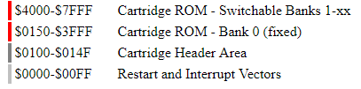
Like before, I’m going with 0x7000 as nothing should ever need to write or in this case read from that address as our rom file will only really be under 16KB. We could really use anything from 0x0000 to 0x7FFF because we the Gameboy flash cart I’ll be using won’t have an MBC, this could allow us to use the other addresses for other things.
kbInput = 0;
if (joypad() & J_A) {
	kbInput |= 0x01;
	printf("A");
}
if (joypad() & J_B) {
	kbInput |= 0x02;
	printf("B");
}
if (joypad() & J_RIGHT) {
	kbInput |= 0x04;
	printf("R");
}
...

sendKey(kbInput);
We might press multiple keys down at once, so each key has it’s own bit that corresponds to it, A is bit 0, B is bit 1, etc, luckily for us there are only 8 keys on the Gameboy which fits perfectly into the usual 8 bit data value that the Gameboy reads/writes on the bus. We also need to send a key (0) even if no key is pressed because otherwise the last key pressed is stored in the V-USB receiver side and it would keep sending that key to the PC.
; Load 0x7000 with value
LD	a,E
LD	(0x7000), a
Having the Gameboy output the key value is easy, just like in the Multi-game loader we output the single data byte at a certain address.
nRF24L01 receiver
I’ve got a fair bit of examples using the nRF24, so it was easy to re-use most of the code to get the wireless link up and running in no time.
...
// Disable auto acknowledgement
mirf_config_register(EN_AA, 0<<ENAA_P0);

// Disable auto re-transmit delay
mirf_config_register(SETUP_RETR, 0);
...
#define mirf_PAYLOAD		1
#define RADDR			(uint8_t *) "wgb01"
#define TADDR			(uint8_t *) "wgbtx"
As part of the setup, we’ll disable auto acknowledgement and auto re-transmit so that communication will be as quick as possible as it’s only going to be one way and the payload size will just be the 1 byte of data which contains the key presses.
if (mirf_status() & (1<<RX_DR)) {
	mirf_CE_lo; // Stop listening

	mirf_CSN_lo; // Pull down chip select
	spi_transfer(R_RX_PAYLOAD); // Send cmd to read rx payload
	spi_transfer(keyPressData); // Read payload
	mirf_CSN_hi; // Pull up chip select
	mirf_config_register(STATUS,(1<<RX_DR)); // Reset status register

	mirf_flush_rx_tx(); // Flush TX/RX
	mirf_CE_hi; // Start listening
}

usbPoll();
if (usbInterruptIsReady()) {
	reportBuffer.data = 0x05; // Center pad, little endian

	// Check for key presses
	if (keyPressData & 0x01) { // A
		reportBuffer.A = 1;
	}
	if (keyPressData & 0x02) { // B
		reportBuffer.B = 1;
	}
	if (keyPressData & 0x04) { // Right
		reportBuffer.X++;
	}
	if (keyPressData & 0x08) { // Left
		reportBuffer.X--;
	}
	...

	// called after every poll of the interrupt endpoint
	usbSetInterrupt(&reportBuffer, sizeof(reportBuffer));
}
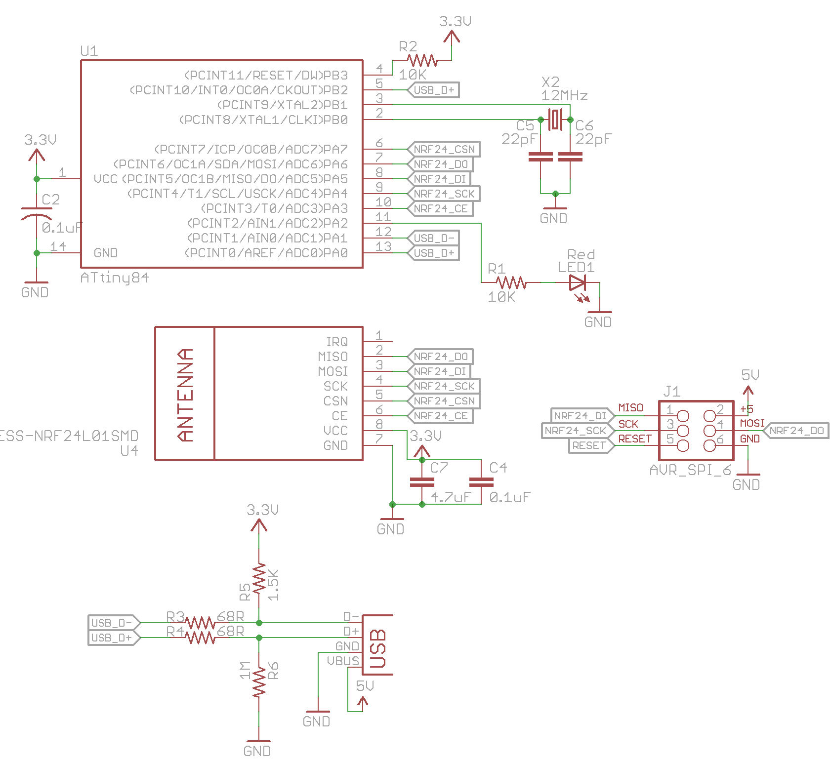
The code on the receiver with the V-USB is pretty simple, after setting up the nRF24, we just check to see if a packet has arrived and read the single byte out of it. We keep polling the USB until it’s ready for us to send data back to the PC, then we just read the byte we received to see what keys are currently being pressed and that’s it!
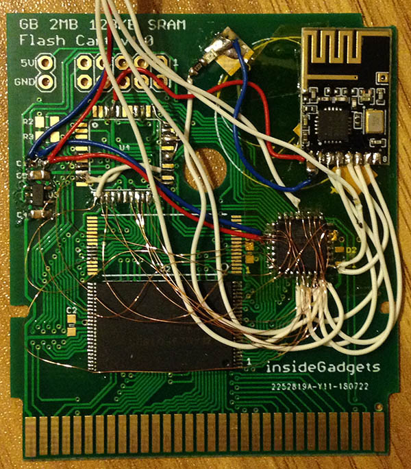
Gameboy cartridge side
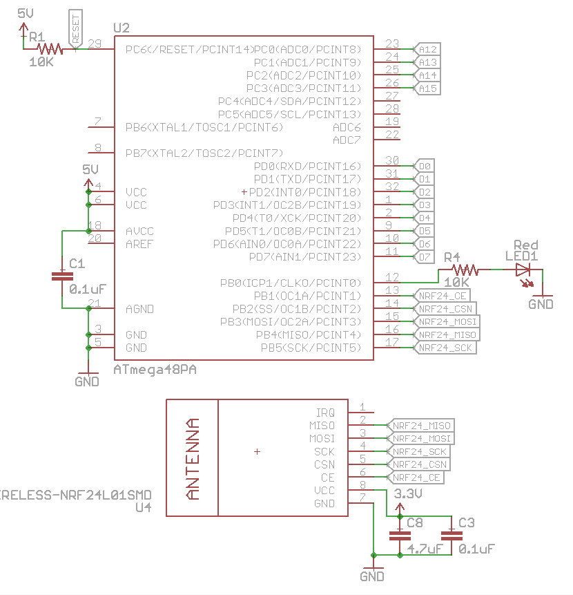
I went with one of my flash cart boards and soldered on the flash chip. I used an ATmega48 which I had in my parts and wired it up to the nRF24 to verify it would send packets when booted up. I changed my ATmega48 so it would remove the divide clock by 8 fuse so that it will run at 8MHz at start up.
if ((PIND & 0xF0) == 0x70) { // 0x7000
Then I wired up the address lines A12-A15 to the ATmega and made it flash an LED when it detected 0x7000. I used PD7 = A15, PD6 = A14, PD5 = A13, PD4 = A12 so we have to AND it with F0 (1111 0000) as we only care about the high 4 bits of that port and then compare that against 0x70. Seemed to work fine so far.
uint8_t kbData = ((PIND & 0x03) << 6) | (PINC & 0x3F);
Now it’s time to wire up the 8 data lines, I went with PC0-PC5 (D0-D5), PD0 – D6, PD1 – D7. Like before we just AND the PINC with 0x3F as we only care about the low 6 bits and AND the PIND with 0x03 and shift it left by 6 so we’ll get a complete 8 bit value.
PORTB |= (1<<LED);
mirf_transmit_data(keyPadData);
PORTB &= ~(1<<LED);
So once 0x7000 is detected, we grab the data that the Gameboy is sending and then transmit that data with the nRF24, the receiver side will receive the data and send the value to the PC.
When testing it out and holding down the A button, it seemed be to hit or miss, sometimes other keys would be pressed as well. I knew it had to be timing related so I analysed the C code into ASM to see how much cycles everything took, I’ve done this a few times before.
if ((PIND & 0xF0) == 0x70) { // 0x7000
 292:	89 b1       	in	r24, 0x09	; 9
 294:	80 7f       	andi	r24, 0xF0	; 240
 296:	80 37       	cpi	r24, 0x70	; 112
 298:	e1 f7       	brne	.-8      	; 0x292 <main+0x2>
As we can see just doing the AND and the compare to PIND and we’ve already lost 2 cycles, then another cycle for the compare.
uint8_t readAddr = PIND;
asm volatile("nop");
uint8_t kbDataButtons = PINC;
uint8_t kbDataStartSelect = PIND;

if ((readAddr & 0xF0) == 0x70) { // 0x7000
	uint8_t kbData = ((kbDataStartSelect & 0x03) << 6) | (kbDataButtons & 0x3F);
	mirf_transmit_data(0x00, kbData);
After a bit of tweaking, we just read the PIND address first, delay 1 cycle so that the data we receive is valid (otherwise it’s sometimes incorrect), read some of the buttons and then the start/select buttons. After everything has been read, we can then do the address comparison and send the keypad data along.
One slightly problem remaining is that the start/select data we read isn’t always correct, I guess by the 4th cycle, it’s already too late.
uint8_t readAddr = PIND;
asm volatile("nop");
asm volatile("nop");
asm volatile("nop");
uint8_t kbDataButtons = PINC;
uint8_t kbDataStartSelect = PIND;
So what we’ll do is just add in a 16MHz crystal and change the fuse bits to suit. Upon trying it again, all the data being received was glitchy/incorrect. I played around with the nops and 3 nops was enough for the data to be correct. Now the start/select button works perfectly!
uint8_t readAddr = PINC;
asm volatile("nop");
uint8_t kpDataButtons = PIND;
Though in thinking about all this after I had the prototype up and working, I should have just made PD0-7 be for the 8-bit data and PC0-3 be for A12-A15, so I’ll make that change to the code and schematic and then we can go back to the 8MHz internal oscillator.
13 Oct 18 Edit: Just built the boards, it looks like there is a little glitch every now and then, if you add the WR pin as PC4 and then check for “if ((readAddr & 0x1F) == 0x07)” that seems to solve it.
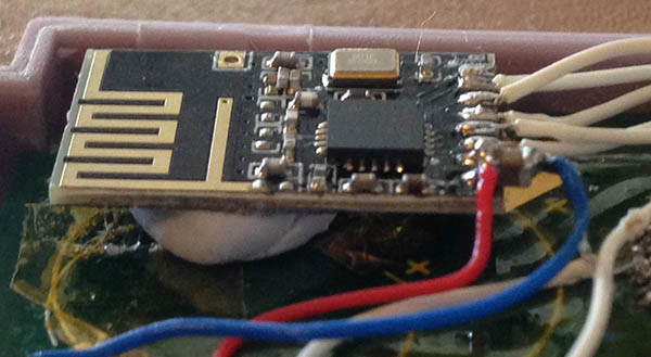
Initial testing of the range was about 2-3 metres which wasn’t great at all. Tried switching channels and data rates without success. We do have a ground plane on the bottom of the PCB, so that would likely affect the signal. I lifted the nRF module off the board by 5mm and range is at least 8 metres now (I couldn’t test any further). If range was an issue, I was thinking about switching to the Si4432 which I know gives much more range.
I was concerned about input lag on the V-USB side but upon testing it on Super Mario Land 2, I wasn’t able to notice any lag at all. I’ll have to continue to test other games but it’s looking good so far.
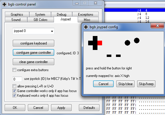
In BGB, for the Joystick to work, you just go to Options > Joypad and configure the game controller.
I’ll might add a small menu to the rom which could allow you to change the receivers address, when the receiver starts up it might listen on a special address for 1 second, maybe also allow for channel changes too.
All in all, this project was a pretty quick turnaround from the idea to the prototype because I had used everything before, took a couple more days to clean up the code, fix some bugs but I will be turning this into a product very soon!
Download Wireless_Gameboy_Controller_v1.0 (licensed under CC BY-NC-SA)
Part 1
Part 2: Adding RF channel/address configuration and more testing
Part 3: Communicating between carts for 2 Player games
Part 4: Adding a Gamecube Receiver
Part 5: Adding a Super Nintendo Receiver
Part 6: Making the GBA TX Cart


[…] Like many retro favourites, the Game Boy is in no way dead — development continues apace through its many fans.But what about the hardware side? This is a particularly interesting one: [Alex] wondered if a Game Boy could be readily used as a wireless controller. Set out to make it happen, the final product is a game cartridge that makes the classic handheld a wireless controller. […]
[…] my stacking skills by ten-fold. That’s probably why I’m so impressed by this hack from Alex Iannuzzi of insideGadgets. Without having to modify or upgrade the original Game Boy or GBA hardware in any way, he managed […]
[…] my stacking skills by ten-fold. That’s probably why I’m so impressed by this hack from Alex Iannuzzi of insideGadgets. Without having to modify or upgrade the original Game Boy or GBA hardware in any way, he managed […]
[…] my stacking skills by ten-fold. That’s probably why I’m so impressed by this hack from Alex Iannuzzi of insideGadgets. Without having to modify or upgrade the original Game Boy or GBA hardware in any way, he managed […]
[…] my stacking skills by ten-fold. That’s probably why I’m so impressed by this hack from Alex Iannuzzi of insideGadgets. Without having to modify or upgrade the original Game Boy or GBA hardware in any way, he managed […]
[…] my stacking skills by ten-fold. That’s probably why I’m so impressed by this hack from Alex Iannuzzi of insideGadgets. Without having to modify or upgrade the original Game Boy or GBA hardware in any way, he managed […]
[…] my stacking skills by ten-fold. That’s probably why I’m so impressed by this hack from Alex Iannuzzi of insideGadgets. Without having to modify or upgrade the original Game Boy or GBA hardware in any way, he managed […]
[…] my stacking skills by ten-fold. That’s probably why I’m so impressed by this hack from Alex Iannuzzi of insideGadgets. Without having to modify or upgrade the original Game Boy or GBA hardware in any way, he managed […]
[…] (which admittedly goes a little over our heads at certain points) you can read the full blog post here. Iannuzzi has also shared a video demonstrating the cartridge in […]
[…] (which admittedly goes a little over our heads at certain points) you can read the full blog post here. Iannuzzi has also shared a video demonstrating the cartridge in […]
[…] (which admittedly goes a little over our heads at certain points) you can read the full blog post here. Iannuzzi has also shared a video demonstrating the cartridge in […]
[…] (which admittedly goes a little over our heads at certain points) you can read the full blog post here. Iannuzzi has also shared a video demonstrating the cartridge in […]
[…] my stacking skills by ten-fold. That’s probably why I’m so impressed by this hack from Alex Iannuzzi of insideGadgets. Without having to modify or upgrade the original Game Boy or GBA hardware in any way, he managed […]
[…] Like many retro favourites, the Game Boy is in no way dead — development continues apace through its many fans.But what about the hardware side? This is a particularly interesting one: [Alex] wondered if a Game Boy could be readily used as a wireless controller. Set out to make it happen, the final product is a game cartridge that makes the classic handheld a wireless controller. […]
[…] inside gadget社公式ブログ […]
[…] Like many retro favourites, the Game Boy is in no way dead — development continues apace through its many fans.But what about the hardware side? This is a particularly interesting one: [Alex] wondered if a Game Boy could be readily used as a wireless controller. Set out to make it happen, the final product is a game cartridge that makes the classic handheld a wireless controller. […]
[…] Want to check this bad boy out first hand, check the developers website. […]
[…] doit cette petite ingéniosité à Alex de InsideGadgets qui propose un tutoriel pour ceux qui aime bricoler. Dans le cas contraire vous pourrez acheter cette cartouche spéciale […]
[…] Inside Gadgets : […]
[…] of an Australian named Alex Iannuzzi. This venture was originally a series of blogs on his website, insideGadgets, but it’s fantastic that he’s decided to sell the finished project. All I can hope is that no […]
[…] um novo propósito aos seus controles antigos? Este cartucho, por exemplo, criado pelo engenhoso Alex Iannuzzi, do insideGadgets, transforma o Game Boy Color e o Game Boy Advance em controles sem […]
[…] Gaming on Batteries, Hack-A-Day, Inside Gadgets Order Link: “Wireless Game Boy Controller” (Inside […]
[…] se ha mostrado como un hombre generoso y ha compartido en su web el diseño y la ingeniería del cartucho. También se incluyen los enlaces del código desarrollado […]
[…] For more details or to place your order, go to InsideGadgets now. If you fancy yourself as a DIY guru and you want to have a crack at building one of these yourself, you are far braver than us, so go here. […]