From our last part we switched tested the Cypress 1Mbit SRAM and read the data out with an Olimex STM32 board. In this part we’ll move to an ATmega to read out the data and use it for triggering the CPLD which will be continually sampling the inputs – the reason is because the ATmega runs slower than the CPLD so a few clock cycles will occur from when it detects the trigger to when it signals the CPLD.
CPLD Side
On the CPLD we can remove the data pins which were being used to test the SRAM and we can link WE and OE pins directly to the SRAM. We’ll re-use the writing pin to tell the CPLD to start capturing data or to be in the read mode, another pin for when we want it to trigger and it records the address minus 50 so that we can see some data before the trigger event.
From our last part we switched to the EPM3064 CPLD for our logic analyser. In this part we’ll use the Cypress 1Mbit SRAM to store the data that we capture.
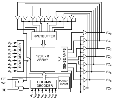
It’s a parallel SRAM which can run at 100MHz which allows us to save time compared to a regular 8 pin SRAM as we don’t have to clock in the address and clock in the data. All we have to do now is set the address pins, feed in the data and set the CE/WE pins low, the perfect job for a CPLD.
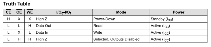
Writing and reading to the SRAM is fairly easy – to write we pull CE and WE low and to read we pull CE and WE low. In all other states the outputs are in high impendance, this allows us the option of adding more SRAM chips.
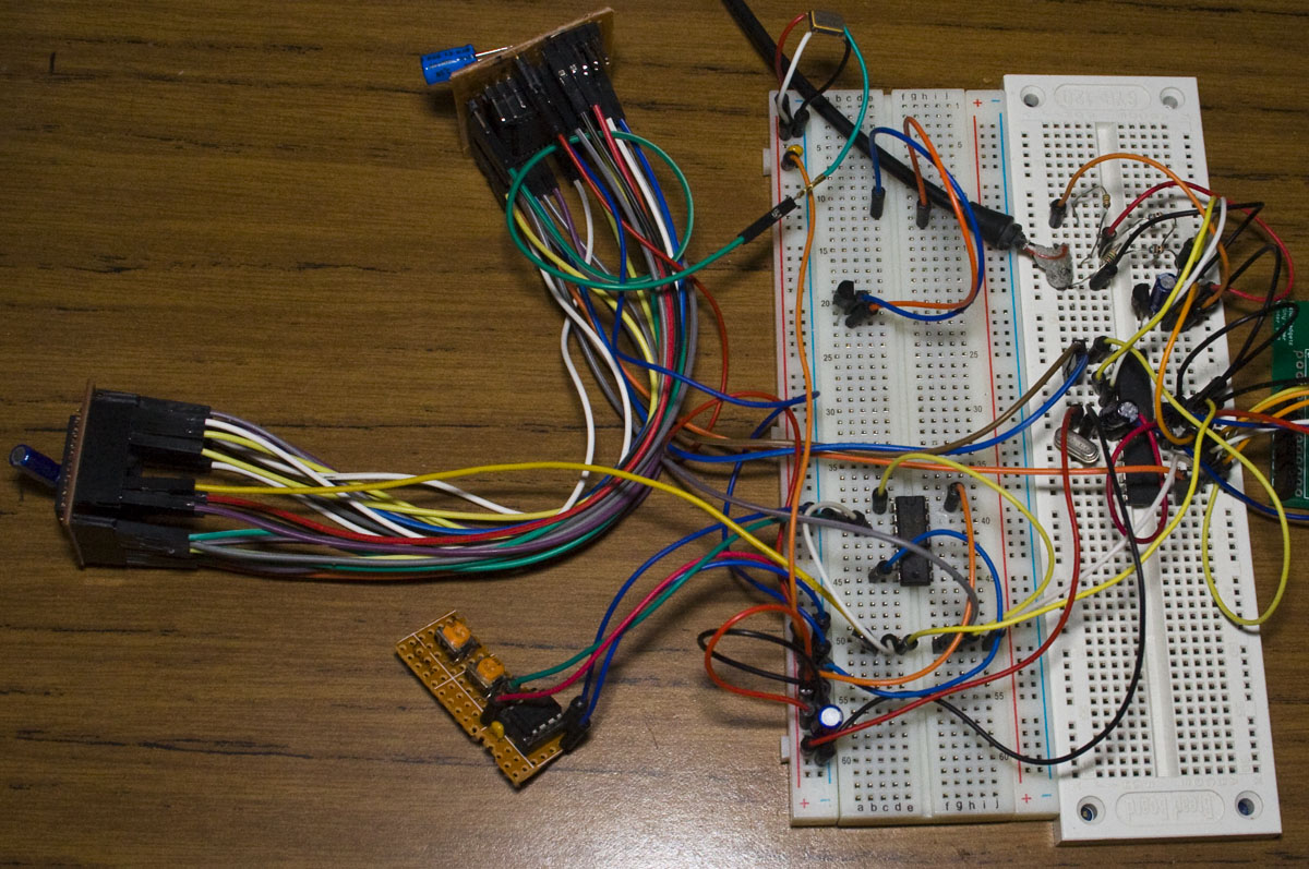
In order to test out the SRAM and the clock feed to the CPLD, I’ll have the CPLD increment an 8bit number which will be written to the SRAM and then read out with an MCU.
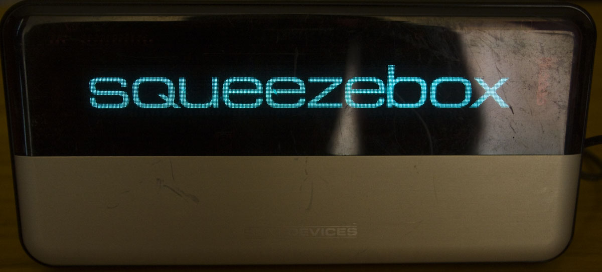
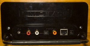
Today we’ll be looking into something a bit different than the regular items we have on – the Slim Devices Squeezebox v3 Network Music Player which has a date code of 2006/12th week. The Squeezebox is a LAN/Wifi network music player which plays music from your computer and outputs it to RCA, S/PDIF or headphones.
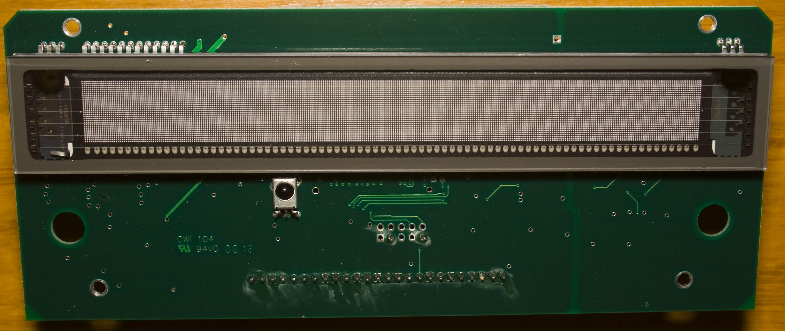
It can also play internet radio and also doubles as an RSS news ticker. The screen is a VFD which looks very nice, maybe I can use it for a project.
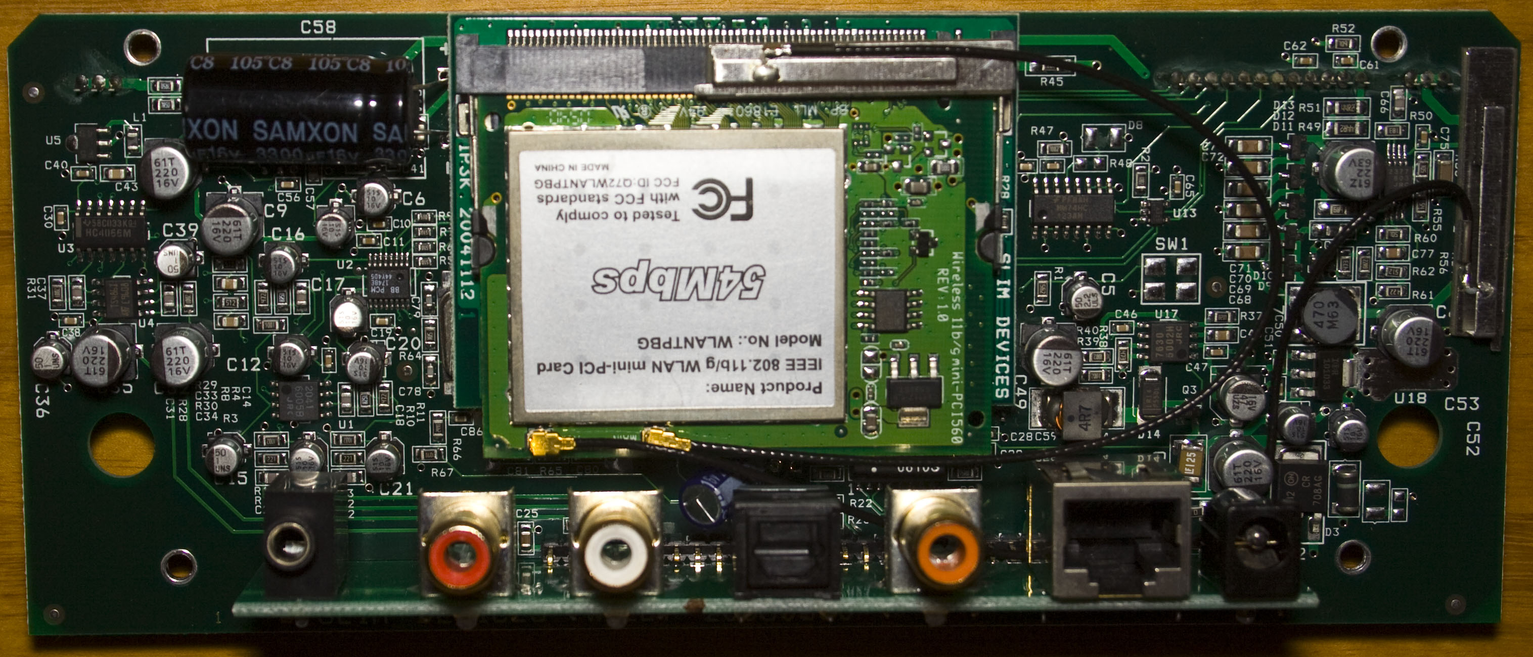
Looks like we have an IR sensor at the front, on the back we have the Wifi board with two antennas and some chips. We’ve got a large 3300uF 16V capacitor though it’s a Samxon branded one. There is another board underneath with all the processing power which we’ll look afterwards.
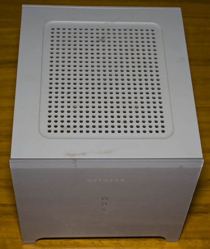
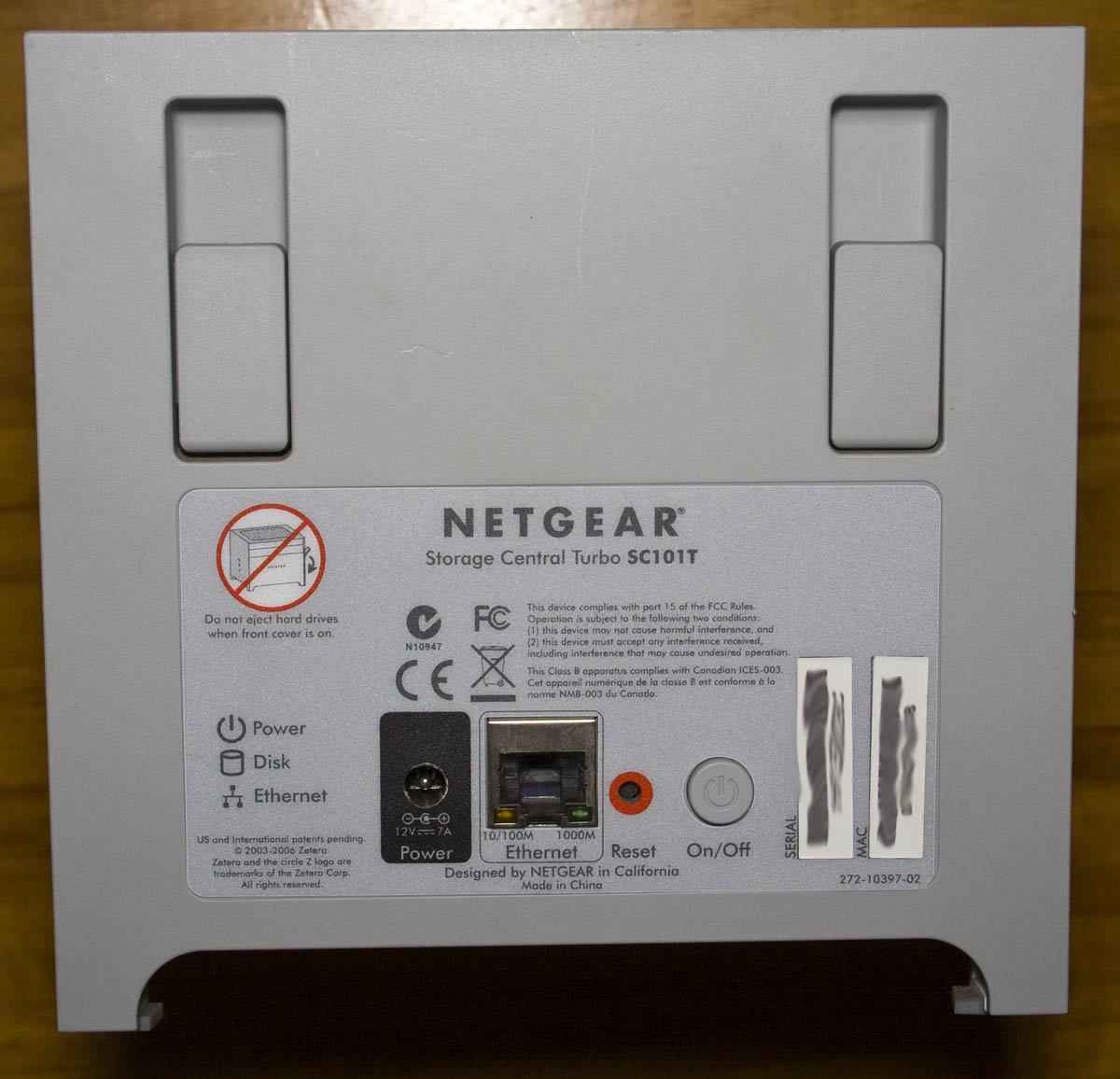
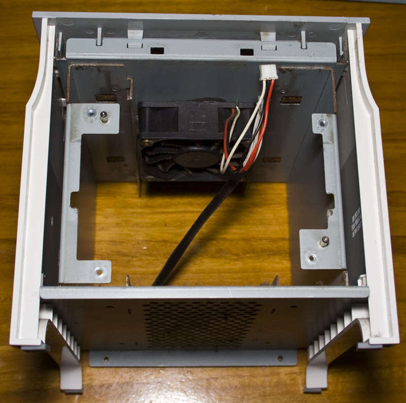
Today we’ll be looking into the Netgear Storage Central Turbo SC101T NAS which is a 2 bay NAS with Gigabit Ethernet. It has a date code of 2006/43rd week.
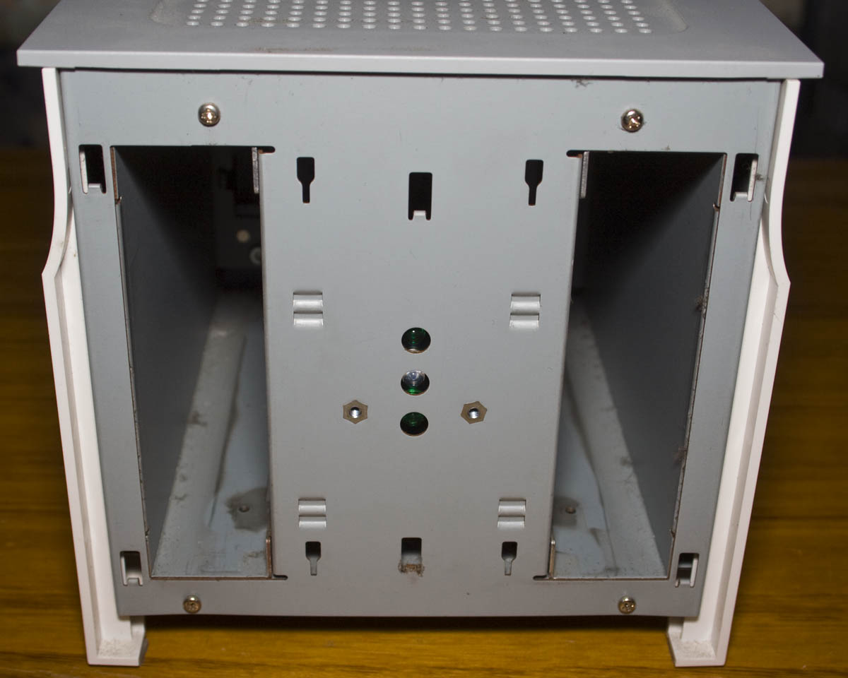
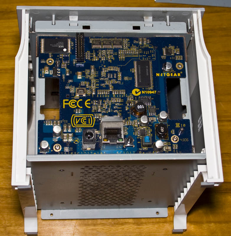
A few screws later and the side panels removed, we’re in.
The 2 hard drives go in the front and we’ve got the PCB at the back with fan near the center top.
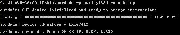
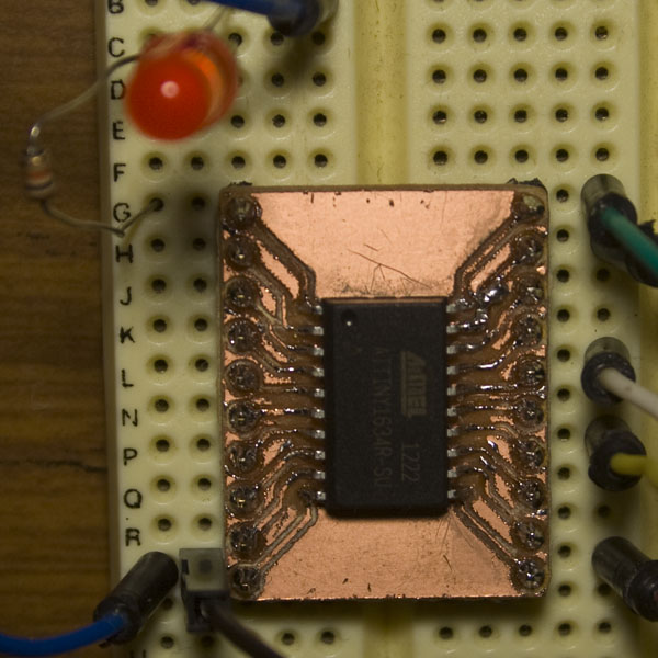
Just a quick post that I’d would be good to mention – If you’re like me and still using WinAVR 20100110, you’ll know it hasn’t been updated for a long time, but what if you want support for the new MCUs like the ATtiny1634? It’s quite simple, just follow the steps below.
Delete all folders in C:\WinAVR-20100110 except for the folders pn and utils
Copy all the subfolders found in C:\Program Files\Atmel\Atmel Studio 6.0\extensions\Atmel\AVRGCC\3.4.0.65\AVRToolchain to C:\WinAVR-20100110
Extract the two files from the AVRDude zip file to C:\WinAVR-20100110\bin
Download this avrdude.conf file and replace the one in C:\WinAVR-20100110\bin (otherwise you will have issues programming the ATtiny1634, fix was taken from this post)
Looks good, here’s the ATtiny1634_Test program I’m using to blink the LED with the watchdog timer.
Back a few years ago when I read the EEPROM of a KVM, we did have an issue where occasionally it wouldn’t switch between computers. A KVM is a keyboard video mouse device that you switch between computers by the press of a button, they can have 2, 4, 8, 16 or more ports. Recently I did have the need for a KVM but we didn’t have one on hand, so I’ve decided it would be interesting to make my own KVM, I’ll start with a 2 port KVM first.
https://www.youtube.com/watch?v=MdbHPUWwgdk
(sneak peak of our prototype in action)
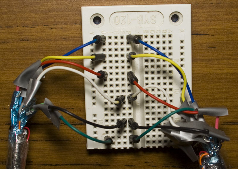
The video side of the KVM will use the VGA, firstly we need to find out how many wires of the VGA we’ll need to pass through.
After slicing some VGA cables, we just need the red, green, blue, hsync and vsync. For each wire, there is a separate ground to it – red ground, blue ground, hsync ground, etc. Firstly I tried connecting all the grounds but noticed some occasional flicker, it’s likely due to the fact that the RGB signals are analog (0.7Vpp) while the H/Vsync are digital and mixing the grounds can cause issues, you normally hear this all the time – separate analog and digital grounds when laying out a PCB. After separating them to RGB and H/Vsync grounds, it works good now.
On Mothers day, I had this idea that it would be fun to make a little LED heart to light up with various animations and would be powered from a coin cell. The board would just be about the same size as the coin holder.
(sneak peak of the end result)
The first step was choosing the MCU, we could go with an ATtiny84 and have an LED on each pin but it’s fairly big, an ATtiny25 with shift registers would work but that would take up most of the board. We can use a technique in which you could configure a series of LEDs in such a way that you only need a few pins to control more than double the LEDs when you reach 4 pins – it’s called charlieplexing.
By configuring both ports as outputs and having one source current and the other one sink current we can effectively control both LEDs depending on which port does what. To calculate how many LEDs an number of pins can control you can use the formula (n2)-n, so for 4 pins we could control 12 LEDs. When you have 3 or more pins, you need to tri-state the pins that aren’t been used otherwise you may have the wrong LEDs light up.
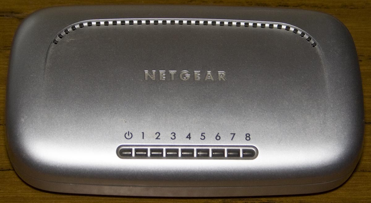
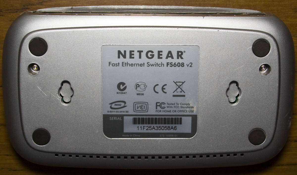
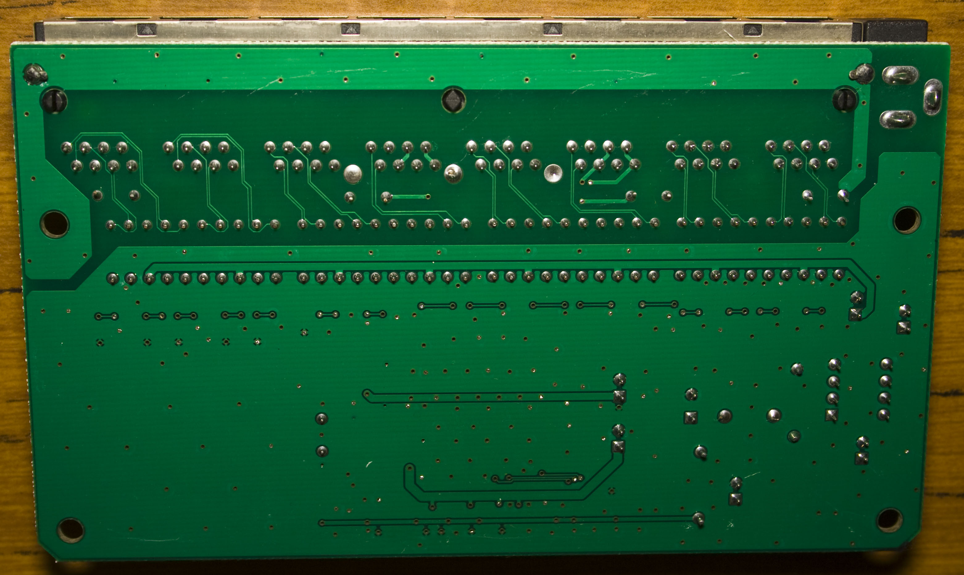
Today we’ll be taking a quick look at the Netgear 8 Port 10/100Mbps Fast Ethernet Switch Switch (FS608 v2) which has a date code of 2005/42nd week.
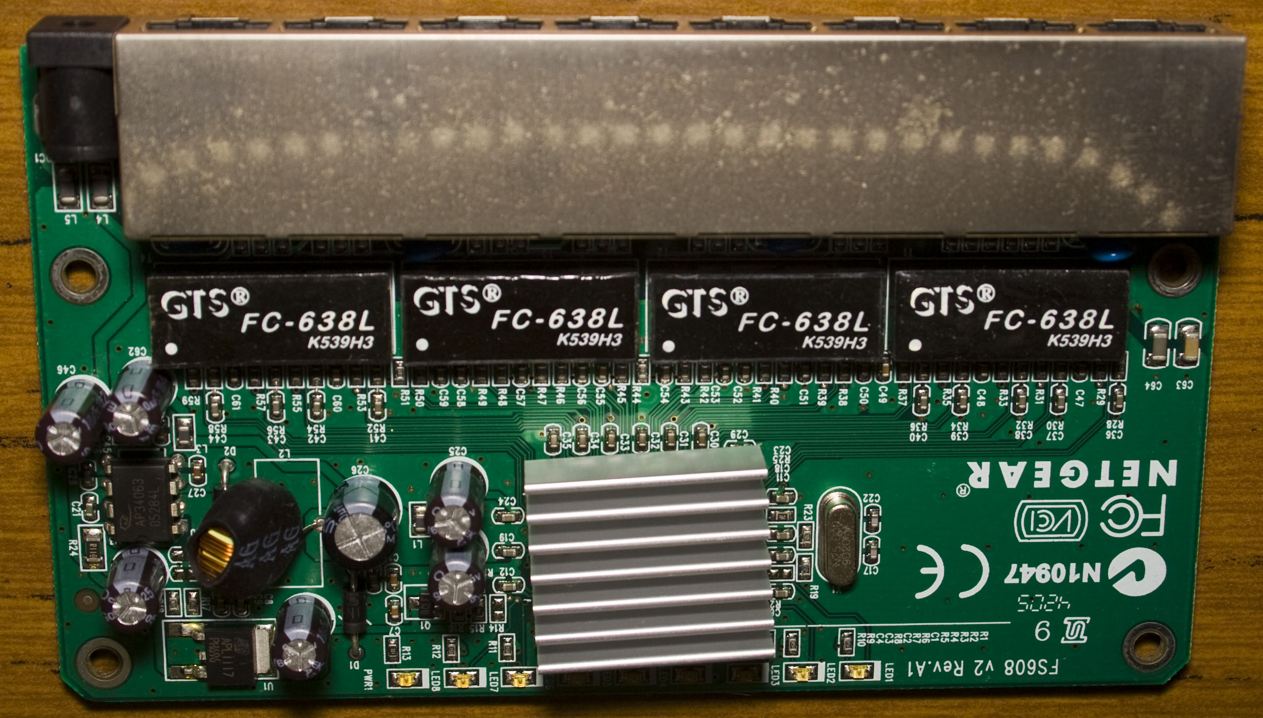
Two torx screws later and we’re in.
As we’ve seen before these old switches use similar parts to one another. We’ve got our AP34063 SMPS and a LD1117 voltage regulator both of which we found on a Netcomm NB6 Router we looked at a little while ago. The inductors legs a quite thin and it’s very easy to move around which isn’t the best.
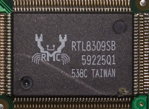
Under the heatsink we’ve got the Realtek RTL309SB – a 9 Port 10/100 switch controller running off a 25MHz crystal, it’s at least a bit different than the IC+ chips we normally see in other switches.
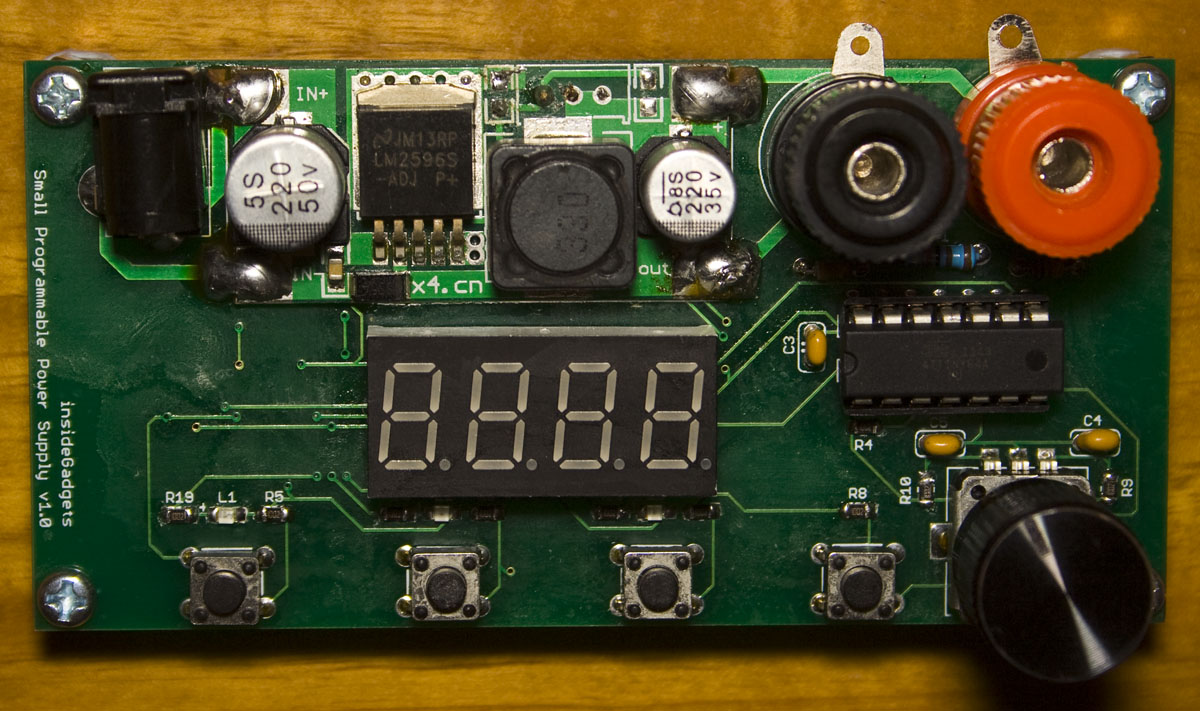
I’ve finally gotten around to releasing the Small Programmable Power Supply (SPPS) v1.0 which I made at least 6 months ago. The SPPS uses the LM2596 module found on Ebay with an ATtiny44 and digital pot to enable adjustable output voltage using a rotary encoder and allows you to have 3 programmable buttons to store preset voltages that you can switch to easily.
There is only limited stock for the time being of the full kit just to see how it sells, the full kit is $29 AUD with $7 shipping (as it’s over 50 grams) and $7 for the PCB only.
From our previous post, we made our remote control and looked at making some improvements however we ended up going back to how sensors communicated to the server before. This time we’re building our prototype PCBs and get to test them all out.
(sneak peak of our PCBs working together) .
Server PCB
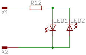
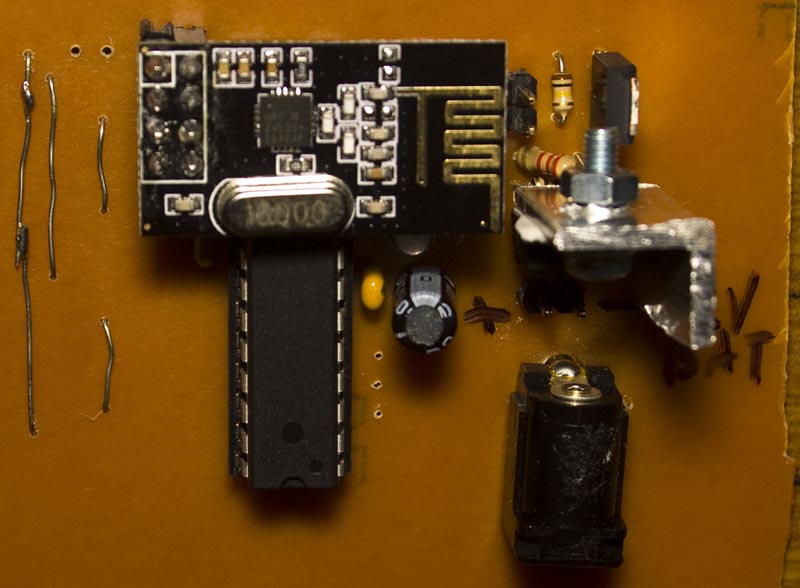
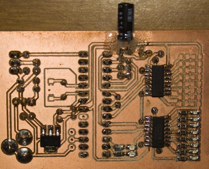
I wanted the server to have a battery backup along with a siren so I took a 15V power adapter and wanted to have some LEDs to display which sensors have checked in with some shift registers to make things easy and now we can have up to 16 sensors. There is also a green LED and red LED used for communication pass or fail, I should of put another LED to shown when the alarm is on. After about a minute or so, the sensor LEDs are reset.
I used the LM317 to reduce the voltage down to 13.5V which is the floating charge voltage for a 12V SLA, the 15V input barely cuts it for 13.5V and doesn’t provide too much current, about 50mA or so. In the end it does run a bit hot so I put in a metal piece on it I had lying around which works good enough. We’ve got a LDO to provide 3.3V to the ATmega328 and nRF24L01+ module, it too runs a bit hot, should have given it more copper. I ended up tearing the pads for the capacitor which is why it’s bodged in there like it is.
AdvanceVGA – Play your GBA on the big screen! Swap out the LCD for our board, solder some wires, connect 5V USB and VGA and you’re ready to go.
GBxCart RW allows you to backup GB/GBC/GBA ROMs, save or restore game saves and re-write supported flash carts. Mini RW option available for GB/GBC only.
Wireless Gameboy Controller – Use your Gameboy, mGB, GBC, GBA, GBA SP, GB Micro, NDS and NDS Lite as a wireless controller on Windows, Linux, Raspberry Pi, etc, and on your NES, SNES, N64, Gamecube and Wii.